Solar & PV Cables are not selected well by starting with a familiar gauge, a product photograph, or a standard number. A good project brief begins with the circuit and route, checks the cable record, the connection method, and the evidence to be provided at the handover. That sequence poses a clear question to the engineering or procurement team that a general guide can’t approve an installed system.
This is an information and documentation route guide. It helps owners, installers, project buyers, and design teams answer cable questions prior to a project-specific assessment. It doesn’t provide a final conductor size, approve burial, certify a product, or substitute for the governing code, equipment instructions, commissioning plan, or the authority having jurisdiction.
The guide’s practical outcome: a route-first specification brief and a controlled record trail. Use them to make a more precise supplier or engineering request, not to turn incomplete information into a cable approval.
1. What Do “Solar,” “PV,” and “PV Wire” Mean in a Project Specification?
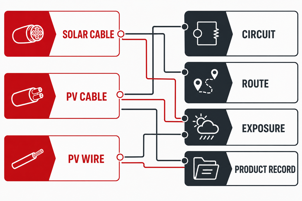
In a project specification, “solar cable,” “PV cable,” and “PV wire” are starting terms, not complete selection instructions. The team still has to identify the circuit, voltage system, route, environmental exposure, product record, and project need. The name can identify a product family and leave the installed application unresolved.
Regarding IEC 62930:2017, for example, the public record states single-core cross-linked insulated and sheathed cables for the DC side of photovoltaic systems up to 1.5 kV DC. It also states a normal continuous maximum conductor temperature of 90°C and a limited 20,000-hour period at 120°C. Those facts are within the scope of that record. They, on their own, cannot approve a certain cable, connector, route, or project.
1.5 kV DC: The stated maximum system-scope in the public record.
90 °C: the stated normal continuous maximum conductor temperature.
120 °C: a stated limited-condition temperature in the same record.
20,000 h: the stated duration connected with that limited condition.
Start by writing a plain-language circuit sentence: “DC string conductor from identified array segment to identified combiner, with route and installation method to be verified.” If the team can’t write that sentence, it’s too early to treat a label as a selection answer. Keep the label, then add the missing project facts.
Decision capsule: IEC 62930’s 1.5 kV DC scope is useful when it matches the question being asked. A cable name, a voltage marking, and a project decision remain three different records. The practical risk is a mismatch between the product label and the installed duty, especially when a 1.5 kV DC scope statement is treated as approval for the route. The next step is to examine the actual project requirement against the applicable product documentation.
2. PV Cable vs. Solar Wire: Where the Naming Comparison Ends
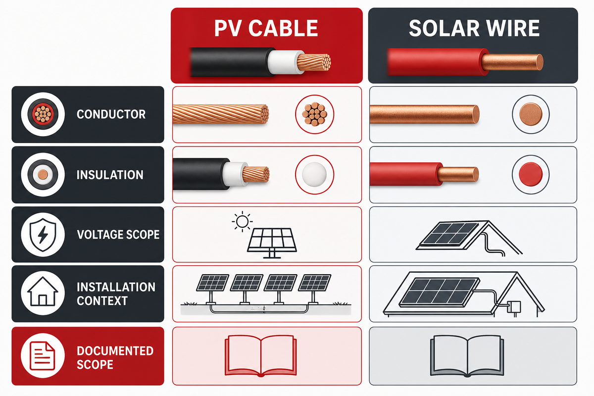
PV cable versus solar wire is typically a terminology question first and a construction-and-scope question second. This comparison checks what the product records actually say about conductor construction, insulation, voltage scope, and installation context. It shouldn’t assume that two items are interchangeable merely because they’re marketed both for solar work.
Comparison point
What to record
What not to infer
Product term
Exact wording from the datasheet or marking.
That a marketing name confirms all project conditions.
Conductor
Material, class, and stated cross-section range.
That every terminal or splice accepts it.
Voltage record
Rated system context and source document.
That a higher printed number approves the whole route.
Temperature record
Stated test or standard scope.
That the site duty is automatically covered.
Environmental statement
Exposure language and stated limitations.
That any outdoor, underground, or immersed route is allowed.
Connector interface
Series, conductor range, and assembly instruction.
That similar-looking connectors mate correctly.
Support method
Route support and protection evidence.
That the cable remains protected after installation.
Certificate or listing
Product identity and stated certification scope.
That it replaces project approval.
Project decision
Responsible reviewer, requirement, and acceptance record.
That a general guide made the decision.
UL Solutions notes that different global regulatory requirements can determine which photovoltaic cables are appropriate, and it distinguishes testing and certification records from the product-selection conversation. See its PV cable testing and certification overview. Therefore, a comparison should end with a request for project evidence for the application cable, rather than a verdict based solely on naming.
Document typography and terminology. The data sheet may write 10AWG while another writes 10 AWG; neither spelling settles the electrical duty, route, or interface. Preserve the wording as is, and analyze the construction and the project.
Decision capsule: The comparison table can reveal gaps, but can never close them. If the product record names a 4 mm² or 10 AWG construction, the project still needs its own current, route, terminal, and installation context before a responsible selection can be made.
3. Build a Route-First Specification Brief Before Choosing a Cable
The route-first specification brief gathers the facts that affect cable suitability before the team requests a response from a product supplier. It comprises electrical duty, physical route, environment, interfaces, and governing documents and records. This hopefully will avoid the common failure mode of assuming that the conductor size is the entire specification. For a procurement team, the practical risk is rework because a supplier can answer an incomplete RFQ without resolving route exposure or terminal compatibility. Even a certification record cannot fill those project-specific gaps.
Name the circuit. Provide the DC load, duty, source and destination, maximum voltage, and design current from the responsible design record.
Draw the route. Show length, transitions, and the location and nature of the structures. Show the location of exposed and protected portions along the route, and show protection changes.
Describe exposure. Show the conditions of temperature, ultraviolet, moisture, contact with chemicals, and motion along with the conditions of the real installation.
Identify interfaces. Show the connector series, terminal or splice, the nature of the conductor, instructions for assembly, and the support hardware.
Identify decision owners. Show the project specification, the governing documents, the equipment, the commissioning plan, and the person or the team that approves every open item.
The U.S. Department of Energy’s cable-management guidance places an emphasis on route conditions, support, length, bundling, bend radius, insulation and exposure, as opposed to a generic single cable option. Its DC-string cable-management guidance can aid in developing a review list. It isn’t an approval for a specific route.
The solar panel circuit can be a DC power path to a combiner and inverter, while another project could identify an endpoint at a charge controller. When dealing with controller or power-system cable questions, record the actual device and function rather than assuming every question has the same answer.
Decision capsule: The brief that includes a 50 m route, but omits current, exposure, and terminal information, is incomplete. The best commercial handoff is a bounded list of known facts plus open questions, each assigned to an accountable source or project owner.
4. Cable Size Starts With Electrical Inputs, Not a Familiar Gauge
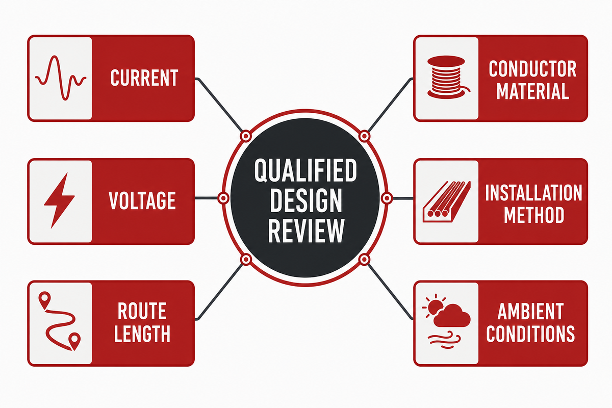
Cable size starts with electrical inputs and conditions of use, not with a known answer of 8 AWG, 10 awg, or a 12 AWG answer. Record current, voltage, route length, conductor material, installation method, ambient conditions, grouping, permitted voltage-drop criterion, and governing requirement before a qualified designer determines a conductor size.
Sandia explains that DC wiring losses arise from cable resistance and follow the I²R relationship. That gives a useful, source-backed illustration: with the same resistance, a hypothetical increase from 10 A to 20 A changes the current-squared term from 100 to 400, or four times the loss term. This is mathematics, not a cable-size recommendation. The actual resistance, route, temperature, installation method, and project constraints still matter. See Sandia’s DC wiring-losses guide.
All elements of a conductor should be considered at the same time along with the endpoint. The review should name the conductor material and cross-section, and then verify the referenced terminal or splice range and the documented assembly process. The conductor can be electrically evaluated and may still require a separate interface check.
Decision capsule: A stated 15 A design current can’t become a final cable choice without the rest of the installation record. If the missing inputs are guessed, the risk is rework because the I²R result can describe assumptions that do not match the installed conductor, temperature, or route. Review the circuit duty, route, installation method, temperature conditions, and applicable project documents together before a responsible project process selects a conductor.
5. Review Long Runs and Voltage Drop Before Locking the Layout
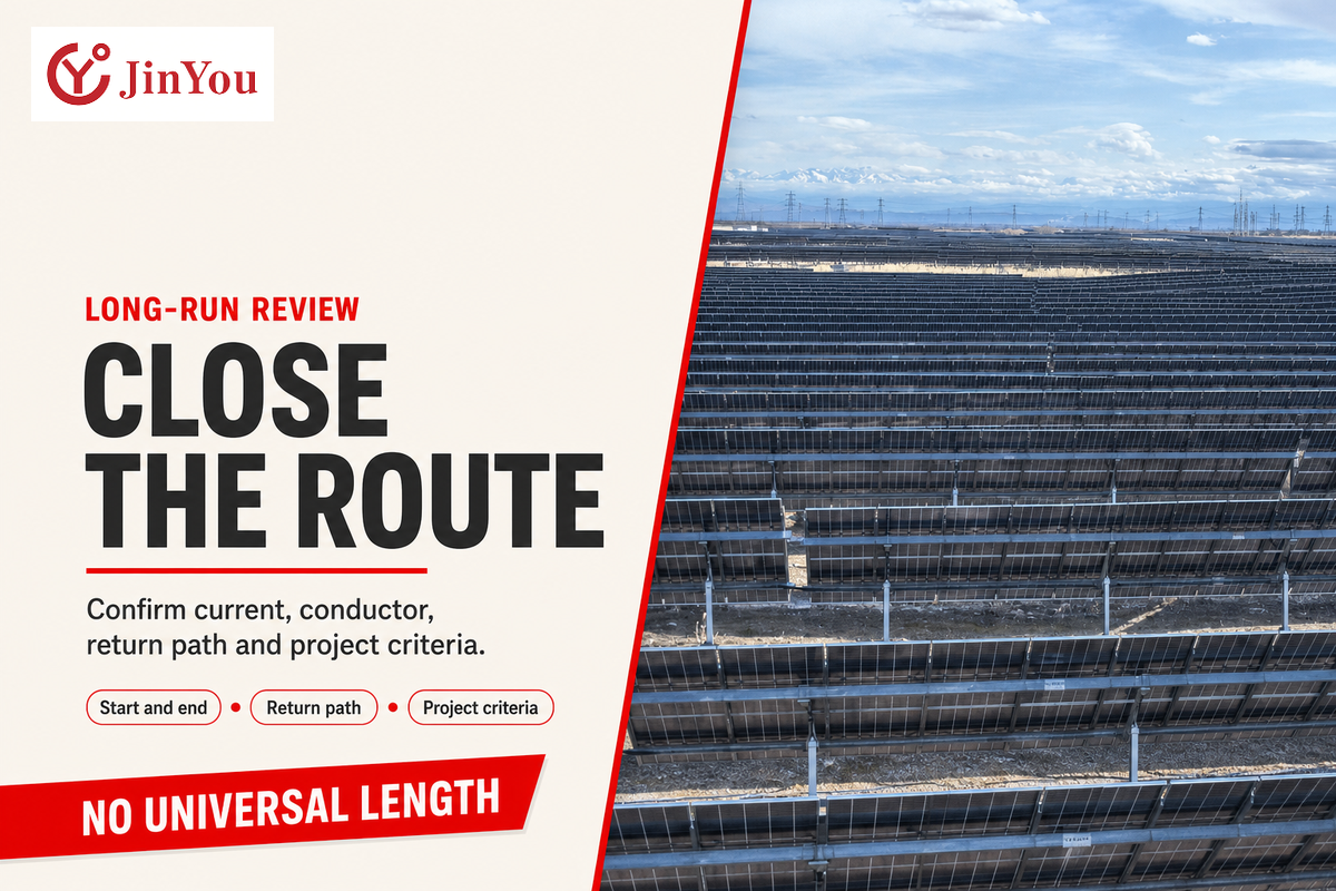
Long cable runs change the electrical review because route length affects resistance and voltage drop. There’s no single correct answer for maximum photovoltaic cable distance without the stated design current and conductor, cross-section, route length, assumption of return-path, voltage system, and project criteria. A good guideline will discuss the input before the output.
The most common relationship is V = I × R. To illustrate this relationship, if we assume a loop resistance of 0.20 Ω and a current of 10 A, we find a drop of 2 V. This does nothing to help a project know whether a 2 V drop is acceptable for a given circuit; that’s a decision for the project. The Texas Department of Transportation describes the relationship of resistance, current, and length in its guidance for calculating voltage drop. Its own example with a given percentage is for a different application and won’t be used here as a PV target.
The route review should tell you if the number shown on a sketch represents a one-way distance, if the total route has been closed, and if the route contains changes in containment or exposure. Those points make “the cable run is long” into a technical question that can be answered.
The same description is useful when a path starts from solar panels to inverters. A note saying “connect solar panels to inverters” should name the start and end points and the source of a closed path, rather than using this as a substitute for a route drawing or a voltage-drop calculation.
Decision capsule: A 60 m one-way route and a 10 m route won’t have the same resistance assumption even if they show the same current on a sketch. Lock the diagram after you record the route assumptions and the electrical inputs for the responsible reviewer.
6. Standards and Markings: Verify the Project Requirement, Then the Evidence
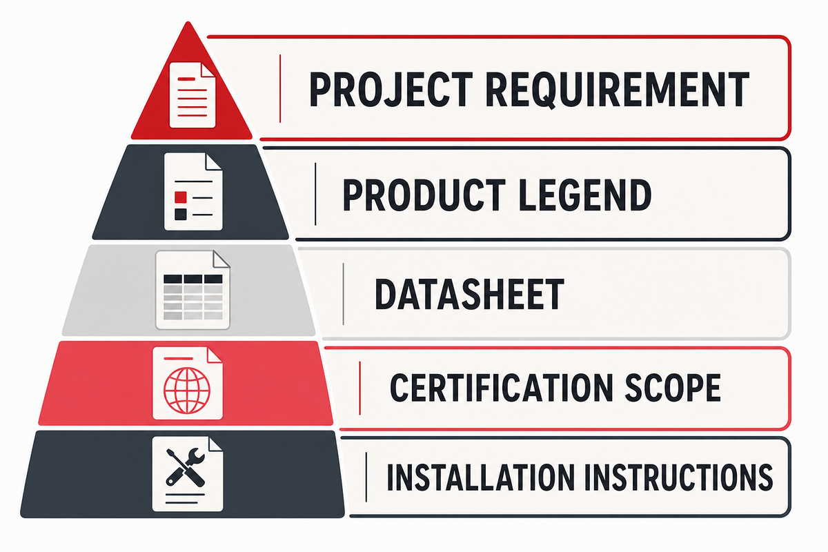
Standards and markings are useful if they’re treated as evidence with a defined function. Compare the project requirement, the product legend, the datasheet, the listing or labelling instructions, the scope of certification, and the installation instructions for the equipment. Don’t expect a single record to do the work of others. The risk is a record mismatch because a standard number, a certification scope, and an installation instruction answer different questions; treating them as interchangeable can send the project review down the wrong path.
In the U.S. workplace context, the cited text of 29 CFR 1910.303 says listing or labelling may evidence suitability for an identified purpose, and listed or labelled equipment must be installed and used according to included instructions. This is an example that’s specific to the jurisdiction. It isn’t to be used to create a general rule or to substitute for a project approval decision.
DOE wording is important because a marking or certificate record belongs in the documentation layer. It doesn’t make the delivered cable record a commissioning output. Ensure separation of the evidence hierarchy: product legend and technical record, application of cable, certificate scope, project need, installation evidence, and the necessary commissioning and approval process.
Construction ranges also need their source boundary. UL Solutions summarizes EN 50618 as flexible cable from 1.5 mm² to 240 mm², and describes IEC 62930 as covering flexible stranded cable from 1.5 mm² plus stranded cable from 16 mm², up to 400 mm² in its stated scope. Those published ranges do not select a conductor for a project; they identify why the exact record and installation question must be checked together.
Decision capsule: A printed standard reference and a 1.5 kV DC scope statement may be valuable evidence, but neither will substitute the application of cable or the project decision. Each record must be aligned with the question it’s designed to address. Keep the other unanswered questions visible.
7. Check Connectors and Interfaces as Part of the Cable System
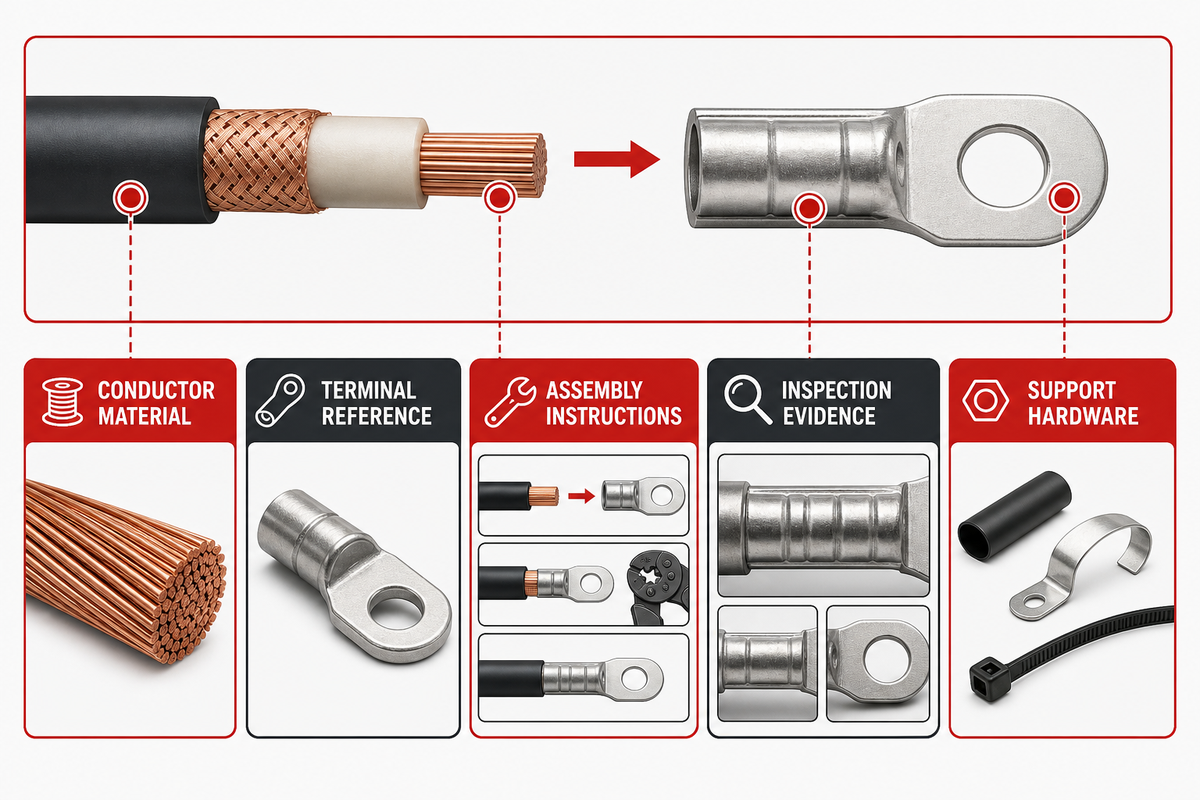
Connector and cable review must cover the interface and address the conductor material, range and connector or terminal reference, assembly instructions and specified tooling or process, inspection evidence and support hardware, and environmental conditions. The presence of nominally compatible components doesn’t imply that the documented field assembly and inspection process was followed.
The DOE FEMP lifecycle guidance considers cable management as part of electrical equipment and separately emphasizes fasteners, electrical connectors, and wire management as installation issues. Its installation and commissioning page also provides a helpful demarcation: project documentation, array testing, and whole-system testing are distinct activities.
The terms solar connectors, MC4, and mc4 connector may help a reader identify an interface issue. They don’t make one connector series interchangeable with another. Keep the current assembly instruction and conductor range in the record.
Interface record
Question to close
Evidence to request
Connector series
Which documented product family is in use?
Product and project reference.
Conductor range
Does the referenced interface cover the actual conductor?
Datasheet and terminal record.
Conductor material
What material is identified at the interface?
Product documentation.
Assembly procedure
Which instructions govern the assembly?
Current manufacturer instructions.
Tool or process
What documented process applies?
Project-controlled assembly evidence.
Seating and closure check
What inspection record is required?
Inspection or commissioning plan.
Support hardware
How is the cable protected along the route?
Route and support record.
Environmental exposure
What can affect the interface over time?
Site and product evidence.
Conductor identification
How are records tied to the correct circuit?
Schedule, drawing, or inspection record.
Decision capsule: IBTS reports wire-management failures on 38% of the PV projects in its inspected population. While this isn’t a general rate, it provides a useful example: don’t consider a connector purchase the terminus of the cable system review. Instead, preserve assembly, routing and inspection evidence.
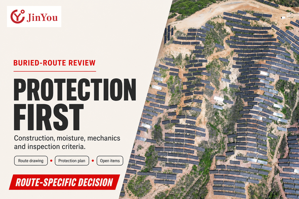
8. Can You Bury Solar PV Cable? Route Protection Comes Before a Yes-or-No Answer
Whether a solar PV cable can be buried depends on the documented cable construction, route protection, moisture and mechanical conditions and other requirements, the project design, and the inspection criteria. A generic, online yes or no doesn’t mean that the product is suitable for the particular route. Burial should be a route-specific decision that requires a review.
Before holding a burial or protected-route discussion, assemble the route drawing, product documentation, containment or mechanical protection plan, exposure conditions, entry and exit details, and the authority or project requirement that defines the route. Mark anything that’s concealed, proposed, or unverified. This is more useful than simply extrapolating from a similar looking cable installation.
A floating-PV study that used freshwater and saltwater submersion conditions, including 12 weeks of insulation-resistance testing, offers a useful warning about source scope. The study differs from normal direct burial, and is more of a case study, rather than an approval, for that setting. For the study regarding that, see floating-PV submersion.
Decision capsule: A route can be either 1 m or 100 m, but the length of a route doesn’t determine whether burial is appropriate. The relevant decision also requires the protection plan, the governing requirement, construction records, and the criteria for the inspection of the route. For a procurement review or site inspection, the risk is that a study from one exposure setting is used because it looks similar, even though it does not verify the planned buried route.
9. Use the 3-Record Cable Trail for Document Control, Then Hand Off to Commissioning
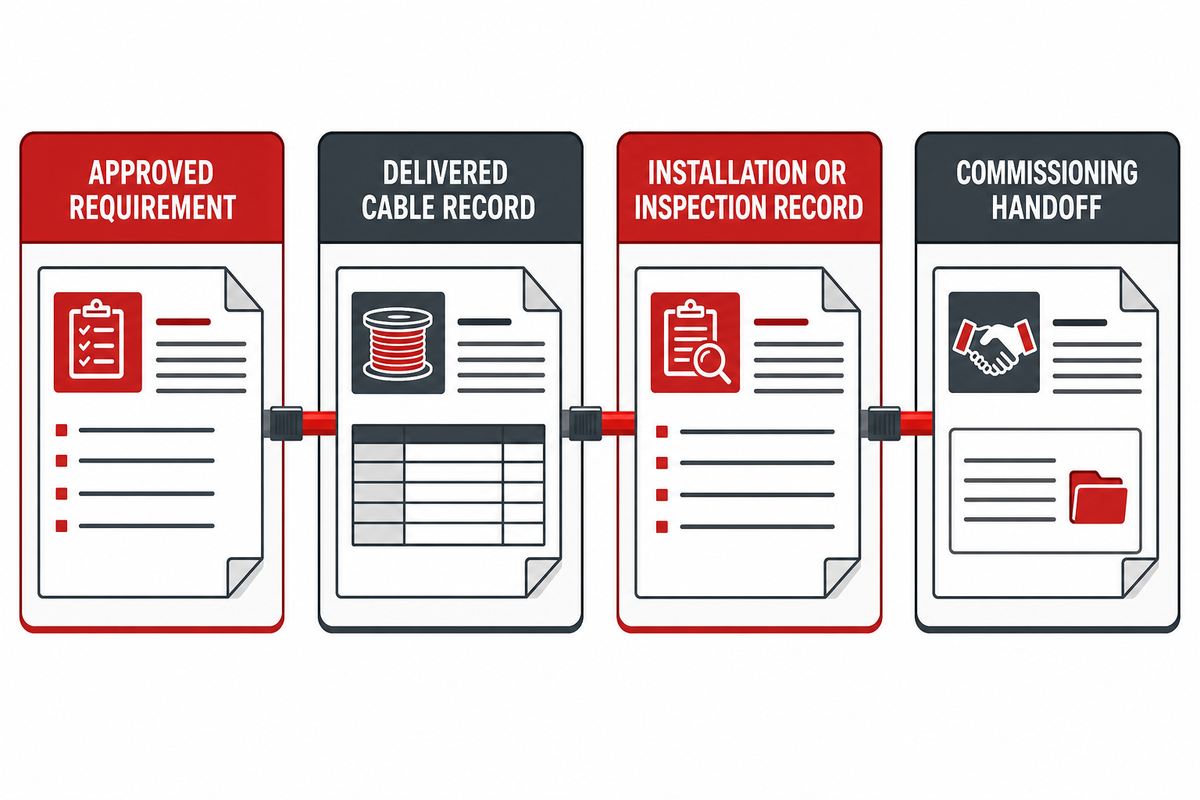
The 3-Record Cable Trail is an editorial, document-control procedure, not an acceptance procedure owned by an authority. It connects the approved project requirement, the cable record, and the Installation or Inspection record. The Trail helps a team identify a record discrepancy while leaving the authority decisions to the required project process; the procurement risk is a record mismatch because the delivered cable, approved drawing, and inspection note can each be valid on their own while referring to different revisions or interfaces. Before handoff, the supplier, inspector, and project owner therefore need the same controlled identifiers.
Approved requirement: retain the controlled specification, drawing revision, standard reference, and any stated project criteria.
Delivered cable record: retains the product identification, marking, datasheet, applicable certificate or listing, and purchasing or submittal reference.
Installation or inspection record: retains route reference, interface or support observations, conductor identification record, and any visible limitations.
The handoff matters. DOE FEMP lifecycle guidance treats project records, array testing, and whole-system performance testing as separate commissioning activities. A three-document check might help in setting up some of those discussions. That set of documents can’t prove the existence of a crimp, concealed route, a measurement, or an acceptance criterion.
Decision capsule: Three controlled documents can connect a 2026 drawing revision, delivered-cable datasheet, and installation note. They can’t substitute for the commissioning plan or the decision authority for the project. Label the approach as document control and specify the handoff.
10. What Current Search Demand Signals Mean for a Solar Cable Guide
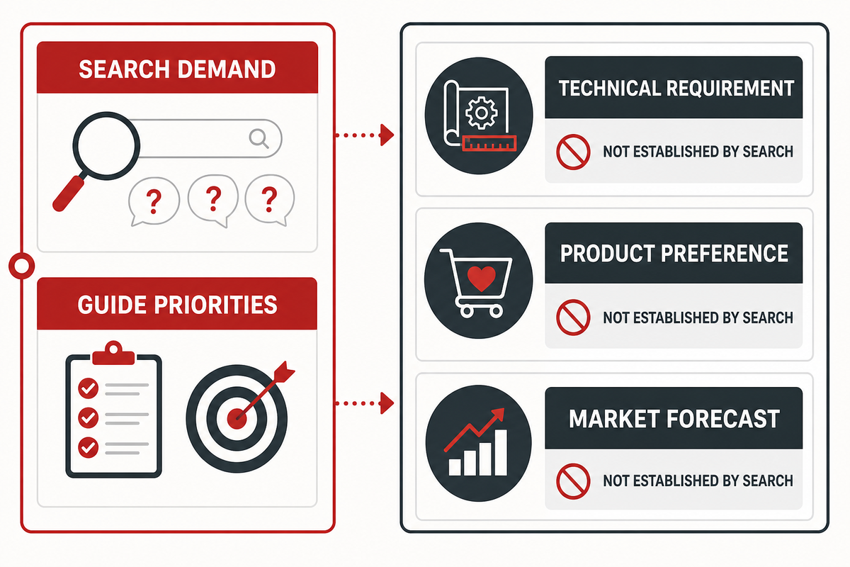
Current search demand helps prioritize the questions the accompanying guide should address, but it doesn’t fulfill a technical requirement, product preference, or market demand forecast. For this situation, the current demand for six months directs readers to solar cable, pv wire, cable size, connector, and route questions across the solar power system. Thus, this article focuses on input and evidence instead of retail extension, cable recommendations.
Restraint applies to industry signals as well. SEIA reported 5.9 GWdc of U.S. utility-scale solar as installed and 6.3 GWdc as contracted in the first quarter of 2026. These numbers don’t forecast a demand for cable. They provide support for editorial decisions to document and address the routing questions that come up in the discussions on utility-scale development. See the SEIA market-insight report.
Once you have a route first brief, a documented interface question and the relevant records, you can move to a project specific discussion. For product and application support, please refer to the Jinyou solar cable solution page. The page is the sales channel; this document is the information channel and provides the required inputs in a project form.
Decision capsule: A search volume of 1,000 for a related phrase can show that readers are asking questions, not that a cable has been selected. Observed query forms such as “Solar panel Cable types,” “Solar panel cables and connectors,” and “PV Wire 10 AWG” are topic labels, not technical evidence. Treating them as selection rules would create a mismatch between search intent and the project record. Use demand data to guide education. Use current project records to make technical and purchasing decisions.
Frequently Asked Questions
What is a PV cable?
A PV cable is a cable described for use within a photovoltaic context, but its suitability still depends on the exact standard or product scope, circuit duty, route, interfaces, and project requirement. For example, IEC 62930 describes a defined DC-side cable scope. That public scope does not approve every cable route or component in a PV system. Start with the circuit and route, then compare the relevant cable record with the project documents.
For a preliminary project, put down the date of the document and the stated voltage and temperature scope, the conductors, the proposed route and the undefined interface. This file gives a supplier, installer, or responsible engineer a traceable starting point. The general cable description doesn’t become an installed system acceptance statement.
What is the difference between solar cable and ordinary electrical cable?
The significant difference isn’t a naming convention; consider the product’s indicated construction, stated voltage and temperature scope, named exposure, connector or terminal interface, and applicable cable and project specifications. A general electrical cable may have a different documented scope from a photovoltaic cable, and a photovoltaic label still doesn’t determine whether a given installed route is acceptable. The responsible project process makes that determination.
How do I choose the right solar cable size?
Consider the current design, circuit voltage, conductor material, route length, cross-section, tolerable voltage-drop, installation method, surrounding conditions, grouping, and overarching constraint. Sandia’s I²R shows why current and resistance can’t be separated. A general format can explain inputs, but a knowledgeable designer or the responsible process on the project must make the determination on the size under the given conditions.
Can you bury solar PV cable?
This can only be addressed on a route-specific basis. Examine the cable documentation, route drawing, mechanical protection, moisture conditions, whether conduit or containment is planned, the local requirement, and the inspection criteria. A floating-PV study or discussion in the forum, or a general product label, can’t be used to justify an ordinary buried route. Document the unknowns and give the governing project or process the evidence needed.
Do PV cable and connector need to be checked together?
Yes. Document the connector or terminal reference, type of conductor material along with the range, documented assembly instructions, required tool or process, support method, environmental conditions, and required inspection evidence. A nominal component match doesn’t prove field workmanship or commissioning. Treat the cable and its interfaces as one documented system, and hand any project-specific decision over to the responsible technical process.
What documents should be checked before PV commissioning?
What’s the requested project requirement, the delivered cable record, along with the installation or inspection record? What do the commissioning plan, cable testing, and the project process require beyond those records? The 3-Record Cable Trail can help support the documentary transfer, but this shouldn’t be used to substitute for testing the cable array, evaluating the overall system, or making an acceptance decision.
Shanghai Jinyou Jinhong Intelligent Electric Co., Ltd. has focused on new energy cable manufacturing since 2006, supporting solar/PV, energy storage, EV charging, and industrial or special-cable applications.
Use this guidance to prepare a clearer engineering or procurement discussion: operating environment, conductor and insulation expectations, route length, voltage, installation method, and project schedule.
Certificate evidence should be matched to the construction being specified. Public certificate evidence applies to H1Z2Z2-K solar cable constructions and should not be read as blanket certification for every JINYOU Cable product family.
PROJECT BRIEF
Move from article to specification
Share the application, required cable family, target standard, quantity range, and delivery window. The team can help structure the next engineering and procurement conversation.