Get in touch with JINYOU Cable Company

-
CALL US +86 181 1623 2461
-
EMAIL sales@jinyougroup.cn
ISO Compliant Quality
Industrial & Special Cables
Built to the construction you specify, not to the nearest item on a stock list.
Six families run on our lines — robot cable, instrumentation and thermocouple compensating cable, variable frequency drive control cable, motor lead wire, heat tracing cable and building wire. Send a drawing, a specification sheet or a sample and we come back with a written construction.
Your drawings are handled as confidential; a mutual non-disclosure agreement is signed before your drawings are opened, and your bill of materials is not shared with third parties.
Quotes returned within 24 hours, reviewed by a cable engineer
Sample lengths in 2–3 weeks after drawing approval
Small batches in 15–25 days
Mutual NDA signed before your drawings are opened
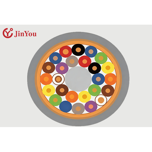
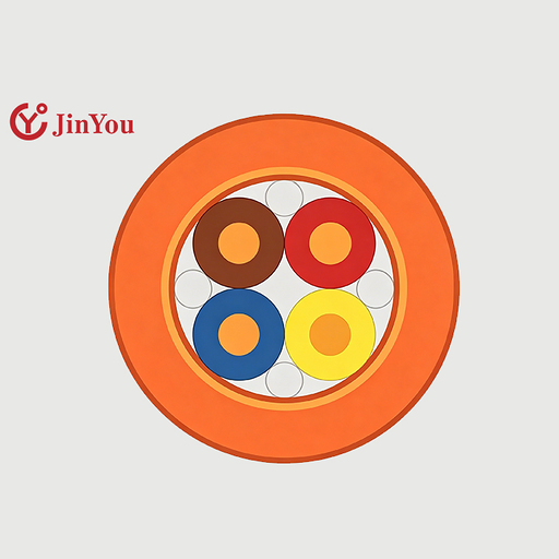
02 // CROSS SECTION
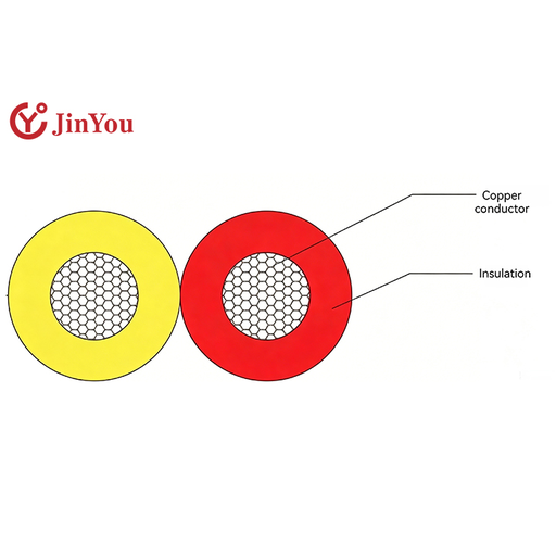
01 // PRODUCTION
Series Production
4–6 weeks, confirmed with your quotation
Minimum Order
No minimum on stocked constructions; made-to-order from 100–200 m per type
Payment
T/T and L/C are accepted; deposit share and balance trigger confirmed with your quotation
Shipping Terms
FOB Shanghai; FCA, EXW, CFR, CIF and DDP quoted on request
Six Cable Families, Sorted by Duty Class
An industrial cable request is easiest to answer when it starts from duty rather than from a product name. Two questions settle almost every enquiry: what is the conductor carrying, and what is the cable asked to survive. We call that pairing the Duty-Class Method, and it routes a requirement to a family in one step.
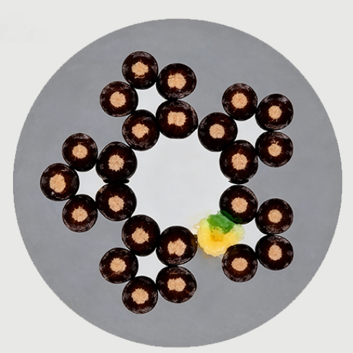
Robot Cable
Halogen-free, plasticiser-free and heavy-metal-free robotic cable constructions for machine tools, energy chains and moving axes — the duty a drag chain cable or a continuous flex cable is bought for. Robot cable types divide by whether the motion is bending, torsion, or both at once. Published model families run YY1001, YY1002, YY1006, YY1007, YY1008, YY2001, YY2002 and YY2006, plus the RO-F5001, RO-F5005, RO-FY5002 and RO-FY5006 series.
Core counts run 2 to 20 and cross-sections 0.14 to 6 mm², including paired constructions such as 4×2×0.14–0.3 mm² and composite builds such as 4×0.75 + 2×0.3 mm².
Explore Robot Cables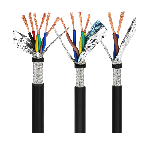
Instrumentation Cable
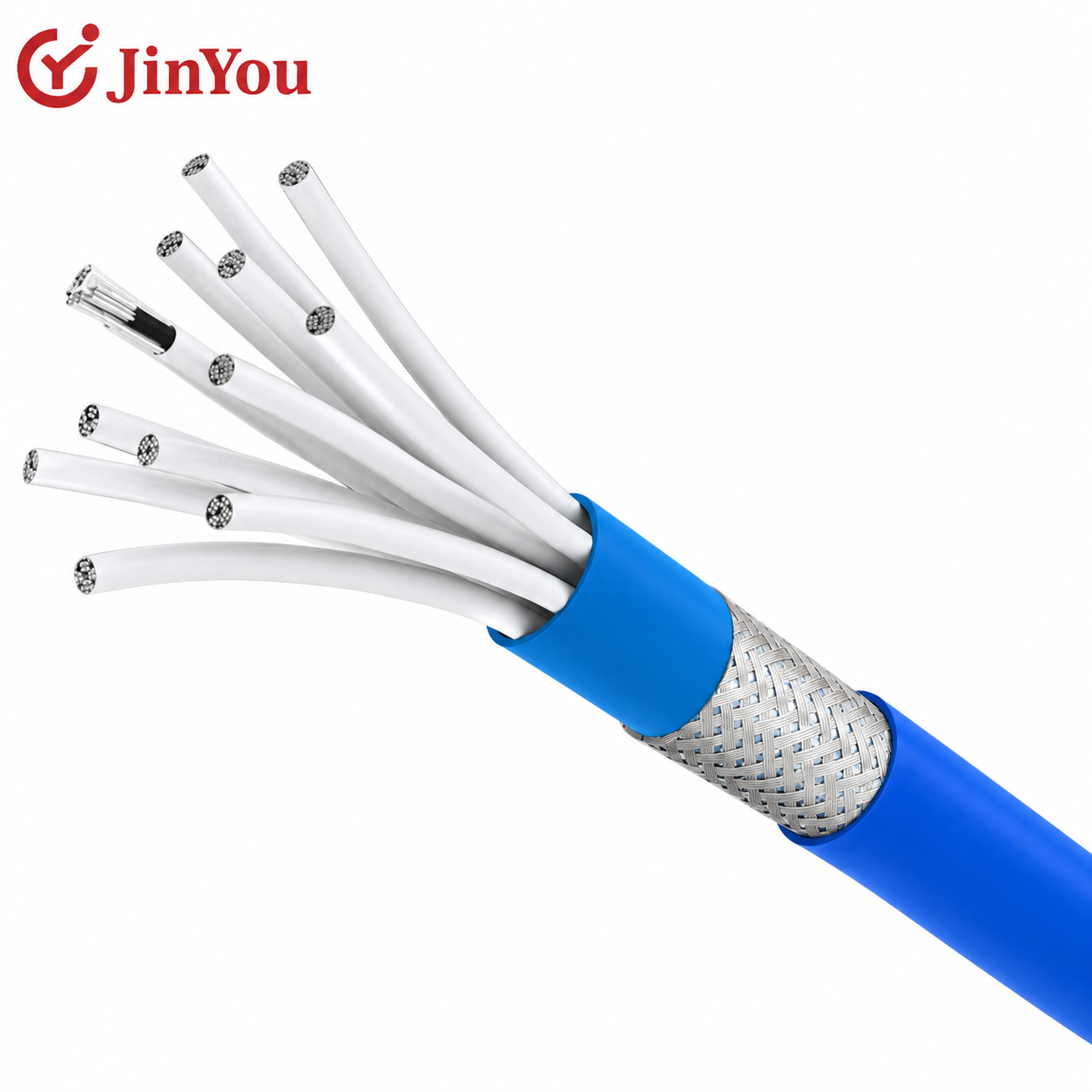
Screened pair and multipair constructions for measurement and control signals in petroleum and chemical process plant. Published model families are BAYP3V, BAVVP3, BAYVP3 and BAYP3VP3 at 1 to 18 pairs, their /22 armoured variants at 4 to 18 pairs, and the KJCP and KJCPR digital detection series at 1 to 16 pairs.
Rated 300/500 V with cross-sections of 0.5, 0.75, 1.0 and 1.5 mm². Classified-location approval, where a project needs it, is set by your specification rather than by this page.
Explore Instrumentation Cables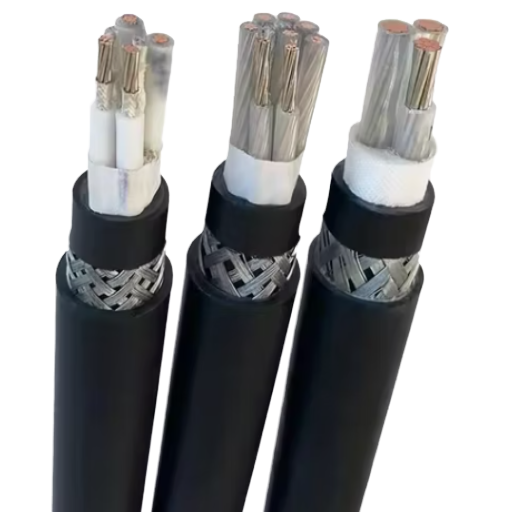
VFD Cable
This is a drive control-circuit family, not a drive-to-motor power feeder. Our own published description is unambiguous: the BPKX range carries the weak voltage and current signals in the control circuit of a variable frequency drive.
Four models are published — BPKXGGP2, BPKXGGPP2, BPKXGP2GP2 and BPKXGPP2GPP2 — at 1 to 20 cores and 0.75 to 2.5 mm², in silicone rubber with double screening, rated to +180 °C maximum and −60 °C minimum.
Explore VFD Cables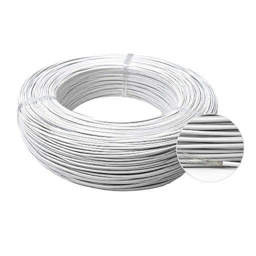
Motor Lead Wire
Silicone rubber and fluoroplastic insulated lead-out wire for class F and class H machines, rated 600 V AC or 1200 V DC. JHG(F)X and the screened JHG(F)XP cover 0.5 to 16 mm²; JYJ125(150) irradiation cross-linked flame-retardant polyolefin covers 0.5 to 120 mm².
Silicone runs −60 to +180 °C and fluoroplastic −40 to +260 °C. Finished insulation withstands a 4000 V AC 50 Hz spark test without breakdown.
Explore Motor Lead Wire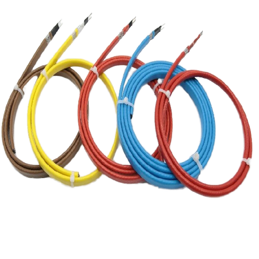
Heat Tracing Cable
Self-regulating tape for pipe freeze protection and temperature maintenance, plus skin-effect cable for long metal pipelines. The self-regulating range publishes BL-10, BL-20, BL-30 and BL-40 in V2 and V3 builds at 10, 20, 30 and 40 W/m.
The skin-effect system covers single-circuit runs from 200 m to 10 km at 15 to 270 W/m, with heat dissipation from 5.0 to 1000 W/m and a maintain temperature up to 500 °C.
Explore Heat Tracing Cables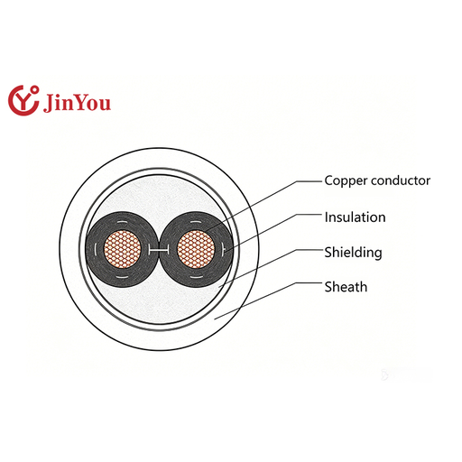
Building Wire
PVC insulated installation wire to IEC and GB constructions — BV, BVR, BVV, BVVB, RV and RVS for general wiring, the ZR- flame-retardant series and the NH- fire-resistant series for circuits that must survive a fire.
Building wire types run from single-core BV and flexible BVR through the flame-retardant ZR- series to the fire-resistant NH- series. Rated 300/300, 300/500 and 450/750 V across 0.5 to 400 mm².
These are IEC and GB constructions; a project written to a North American wiring code needs that stated on the enquiry.
Explore Building WireThe Duty-Class Method
Axis A is the electrical duty — what the conductor carries. Every family sits in exactly one of these four. Axis B is the mechanical and environmental duty — what the installation asks the cable to put up with. A family can sit in more than one.
Axis B describes what your application demands. It is not a performance claim about any particular cable: we publish the construction, and the service limits belong on your drawing.
| Axis A — Electrical Duty | How to recognise it | What it changes in the construction | Family |
|---|---|---|---|
| Power | The conductor carries working current and the cross-section is set by ampacity | Cross-section steps, insulation voltage class and thermal class lead the design | Motor lead wire; building wire |
| Control | The conductor switches or enables, and carries no load current | Higher core counts at small cross-sections; interference rejection leads the design | VFD control cable; control cores in building wire |
| Signal | The conductor carries a measurement whose accuracy is the product | Pairing, screen layering and capacitance or inductance limits lead the design | Instrumentation cable; thermocouple extension and compensating cable |
| Heat-generating | The cable is the heating element, not a transmission path | Heating core chemistry, power density in W/m and maximum temperatures lead the design | Heat tracing cable; skin-effect pipe heating |
| Family | How to recognise it | What it changes in the construction |
|---|---|---|
| Fixed installation | Laid once and left alone | Conventional stranding class and conventional sheath |
| Continuous motion | Bent, twisted or dragged for the life of the machine | Finer stranding, shorter lay lengths, abrasion-resistant sheath, screen built for movement; the cable management system sets the working bend radius |
| Thermal and chemical exposure | Sustained heat, deep cold, oil or corrosive attack | Silicone rubber or fluoroplastic insulation; low-smoke halogen-free or special sheaths |
Where Each Family Lands
- Robot cable sits at Control or Signal on Axis A, with Continuous motion on Axis B
- Instrumentation and thermocouple cable is Signal, usually in Fixed installation
- VFD control cable is Control in Fixed installation, with thermal exposure at the drive
- Motor lead wire is Power with Thermal exposure, on class F and class H machines
- Heat tracing cable is Heat-generating by definition, with Thermal exposure
- Building wire is Power or Control in Fixed installation
Shielding, Screening and Armour Options
More screening is not automatically better screening. Where a screen is grounded decides as much as what it is made of, and the correct answer changes with the frequency of the EMI you are fighting.
One consequence is worth stating before the table. A shielded VFD cable on the feeder side and a screened control cable on the control side are two different purchases, and a drawing that asks for “VFD cable” without saying which one has not specified either.
Where the Screen Is Grounded
Earth an instrumentation screen at both ends and any difference in ground potential between those two points drives a current along the screen itself. At power frequencies that circulating current couples noise into the very conductors the screen was fitted to protect. Earth it at one end and the loop is broken, which is why single-point earthing is the classic rule for low-frequency analogue signals.
Reverse the frequency and the rule reverses with it. For high-frequency interference, bonding both ends gives the screen a low-impedance path and better immunity, which is why drive power feeders are terminated at both the drive cabinet and the motor. That is a trade-off, not a quality ranking.
The practical consequence is blunt: a screen bonded at the end the project did not intend does nothing for the interference you are actually fighting, and on a low-frequency loop it can make the reading worse. We build the screen so either philosophy can be executed, and we ask which one your project specifies.
This subject has a standard of its own. IEC TR 61000-5-2 is the IEC’s technical report on the earthing and cabling of electrical and electronic systems for electromagnetic compatibility, and a project that hands you an earthing philosophy is usually working from that family. Tell us which philosophy your specification sets and the screen is built to suit it.
| Screen or armour | Code | What it does well | Where we build it |
|---|---|---|---|
| Copper wire braid | P | Low-frequency interference and mechanical robustness; survives movement better than a foil | In-house, all screened families |
| Tinned copper wire braid | P1 | As above, with tin plating for solderability and corrosion resistance at the termination | In-house, instrumentation and motor lead |
| Copper-plastic composite tape | P2 | High-frequency coverage at low weight; needs a drain wire to be terminated | In-house, instrumentation and VFD control |
| Aluminium-plastic composite tape | P3 | Individual pair screening at the lowest diameter penalty | In-house, multipair instrumentation |
| Braid over tape, double screened | PP2 / GP2GP2 | Both frequency ranges at once; the BPKX drive control range is built this way | In-house, VFD control |
| Steel tape armour | /22 | Mechanical protection for buried and tray runs; changes the bend radius | In-house, instrumentation /22 variants |
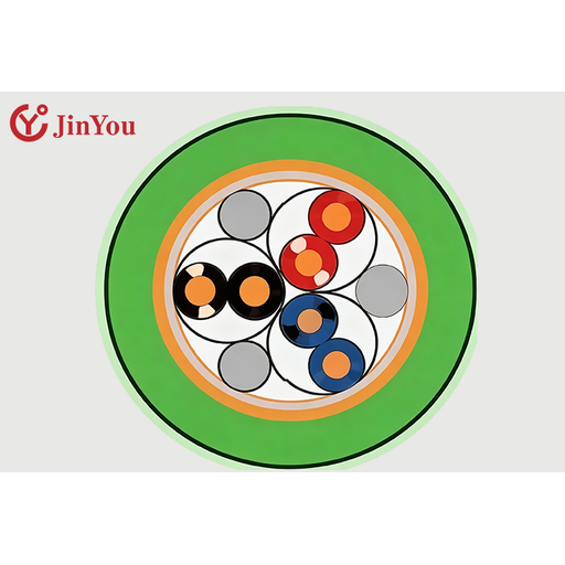
One construction detail belongs to the feeder rather than to us. On a drive-to-motor power cable the ground conductors are often arranged symmetrically around the phases, a symmetrical ground, so the return path stays balanced at the drive’s switching frequency. That is a power-cable construction; the BPKX range we build sits on the control side of the same cabinet.
Termination Geometry Decides the Result
A screen that measures continuous with a meter can still fail in service. A long pigtail behaves inductively at high frequency, so a connection that looks electrically sound at DC becomes much less effective as the interference frequency climbs.
A 360-degree termination gives a low-impedance connection around the whole circumference of the cable and is what keeps screen performance intact at high frequency. That is why we care which screen you are getting: a continuous braid or a braid-over-tape build can be clamped in a gland, a bare foil with a drain wire generally cannot.
“When a customer tells us the screen is fitted but the noise is still there, the first thing we ask for is a photograph of the gland. Nine times out of ten the braid has been combed out into a pigtail and bolted to a terminal, which is exactly the connection that stops working at the frequencies a drive produces.”
Instrumentation electrical characteristics are held to published limits on our screened pair constructions: working capacitance ≤90 pF/m at 1 kHz, capacitance unbalance ≤1 pF/m at 1 kHz, distributed inductance ≤0.6 µH/m.
Interference performance is published alongside them: electrostatic induced voltage ≤1 V under a 20 kV electrostatic field, and electromagnetic interference induced voltage ≤5 µV under a 400 A/m interference field.
Construction Limits and Acceptance Boundaries
The table below is the core construction envelope every family publishes. Family-specific values follow it, and any parameter a family does not publish is simply absent rather than estimated. Voltage classes across the range run from 300V and 300/500 V instrumentation and building constructions, through 450/750 V power constructions, to 600V AC motor lead wire. Nothing on this page is a high voltage cable in the medium-voltage or high-voltage sense; that is a different product family and a different conversation.
| Family | Cores or form | Cross-section or rated power | What we hold |
|---|---|---|---|
| Instrumentation (BAYP3V, BAVVP3, BAYVP3, BAYP3VP3) | 1–18 pairs; /22 armoured 4–18 pairs | 0.5, 0.75, 1.0, 1.5 mm² (about 20, 18, 17 and 16 AWG) | 300/500 V; installed bend radius 6× outer diameter unarmoured, 12× armoured |
| Instrumentation, digital detection (KJCP, KJCPR) | 1–16 pairs | 0.5, 0.75, 1.0, 1.5 mm² | 250 V at power frequency, 50 mA; ambient 0–40 °C |
| VFD control (BPKXGGP2, BPKXGGPP2, BPKXGP2GP2, BPKXGPP2GPP2) | 1–20 cores | 0.75–2.5 mm² (about 18 to 14 AWG) | +180 °C maximum, −60 °C minimum; double screened, silicone rubber |
| Motor lead wire (JHG(F)X, JHG(F)XP) | Single core, screened option | 0.5–16 mm² (about 20 to 6 AWG) | 600 V AC / 1200 V DC; silicone −60 to +180 °C, fluoroplastic −40 to +260 °C |
| Family | Cores or form | Cross-section or rated power | What we hold |
|---|---|---|---|
| Motor lead wire (JYJ125(150)) | Single core | 0.5–120 mm² (about 20 AWG to 250 kcmil) | Irradiation cross-linked flame-retardant polyolefin; 600 V AC 1 minute withstand |
| Robot cable (YY and RO-F series) | 2–20 cores, including pair builds | 0.14–6 mm² (about 26 to 10 AWG) | Halogen-free, plasticiser-free, heavy-metal-free construction |
| Heat tracing, self-regulating (BL series) | Parallel tape, cut to length on site | 10, 20, 30, 40 W/m | 220 V and 380 V builds; bend radius 25.4 mm (1.0 in) at 20 °C, 35 mm (1.4 in) at −30 °C |
| Heat tracing, skin effect | Single circuit 200 m–10 km (656 ft–6.2 mi) | 15–270 W/m; 5–500 kW per unit | Maintain temperature up to 500 °C; cable 10–70 mm²; IP68 |
| Building wire (BV, BVR, RV, ZR-, NH- series) | 1–5 cores | 0.5–400 mm² (about 20 AWG to 800 kcmil) | 300/300, 300/500 and 450/750 V; 70 °C standard, 90 and 105 °C grades |
| Model | Rated voltage | Rated power | Maximum circuit length | Maximum fluid holding temp. |
|---|---|---|---|---|
| BL-10-V2-Q-J3 | 220 V | 10 W/m | 200 m (656 ft) | 150 °C |
| BL-20-V2-Q-J3 | 220 V | 20 W/m | 120 m (393 ft) | 140 °C |
| BL-30-V2-Q-J3 | 220 V | 30 W/m | 100 m (328 ft) | 125 °C |
| BL-40-V2-Q-J3 | 220 V | 40 W/m | 100 m (328 ft) | 100 °C |
| BL-20-V3-Q-J3 | 380 V | 20 W/m | 300 m (984 ft) | 130 °C |
| BL-30-V3-Q-J3 | 220 V | 30 W/m | 230 m (754 ft) | 125 °C |
| BL-40-V3-Q-J3 | 220 V | 40 W/m | 185 m (606 ft) | 100 °C |
Instrumentation Electrical & Thermal Limits
Conductor long-term operating temperature: 70 °C polyethylene, 90 °C cross-linked polyethylene, 70 °C low-smoke halogen-free polyolefin, 90 or 125 °C cross-linked low-smoke halogen-free polyolefin.
Installation ambient not below 0 °C; service minimum −40 °C fixed and −15 °C non-fixed.
Insulation resistance at 20 °C: ≥25 MΩ·km PVC, ≥100 MΩ·km polyethylene and fluoroplastic.
Temperature classification codes 70, 90, 105, 180, 200 and 260 mark the maximum operating temperature of the build.
Thermocouple Extension & Compensating Cable
A thermocouple extension cable uses the same nominal alloy pair as the sensor; a compensating cable uses a less expensive pair matched over a smaller range. This range covers the SC and RC for platinum-rhodium thermocouples, KC and KX for nickel-chromium types, NC and NX, EX, JX and TX.
IEC 60584-3 is the standard that governs this product; it sets identification and manufacturing tolerances for extension and compensating cables, expressed against the e.m.f. versus temperature relationship of IEC 60584-1. For KX over −25 to +200 °C the tolerance classes in that standard are ±60 µV (about ±1.5 °C) for class 1 and ±100 µV (about ±2.5 °C) for class 2.
Our own published table runs on a different scale and is not an IEC class. Over the same range it lists a precision grade of ±44 µV (about ±1.1 °C) and a common grade of ±88 µV (about ±2.2 °C) for KX. State which regime your specification is written to, because a grade name on its own does not say which of the two scales it belongs to.
Loop resistance at 20 °C is published per type and cross-section — KX reads 5.50, 2.20, 1.10, 0.73 and 0.44 Ω/m at 0.2, 0.5, 1.0, 1.5 and 2.5 mm².
Heat-Tracing Temperature & Circuit Limits
Heat tracing cable types split into self-regulating tape, which is cut to length on site, and skin-effect systems that are engineered as a circuit for a specific pipeline.
Sheath withstand temperature is published by sheath code: J3 to 205 °C and J4 to 260 °C. Minimum installation temperature is −50 °C and dielectric strength is 2500 V AC at 50 Hz for one minute.
Thermal stability is published as a cycling result: after 300 cycles between 10 and 99 °C on the black band, and between 10 and 149 °C on the brown and red bands, heat output remains above 90 per cent. Insulation resistance is measured on a 100 m length at 25 °C with a 500 V DC megohmmeter for one minute, with a minimum of 20 MΩ between conductor and screen.
Incoming Material Control and Release Documents
Cable quality is decided before the extruder starts. Four controls run on every order, and they are the same four whether the order is a 200 m sample run or a series release.
Copper and aluminium purity and resistivity are tested before the metal enters the drawing line because conductor substitution is the single most common way a cable stops matching its own datasheet.
Insulation and sheath compounds go through physical and chemical analysis for temperature resistance, ageing resistance and mechanical strength, including tensile strength and elongation at break.
Each raw-material supplier’s qualification certificates and environmental compliance documents including RoHS and REACH declarations are verified before the material is released to production.
Conductor DC resistance is measured on the finished cable and corrected to 20 °C, which is the basis IEC 60228 specifies for the check.
That fourth step is worth a sentence of its own. IEC 60228 relates to the conductor in the finished cable, not to the wire as supplied into it, so a resistance figure taken on incoming stock does not answer the question a buyer is actually asking.
Release Documents
The document set that ships with your order is agreed in the quotation. Tell us what your project file has to contain and we confirm in writing which documents accompany the drums and which are issued separately.
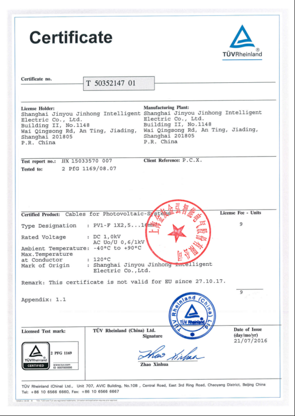
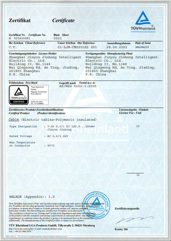
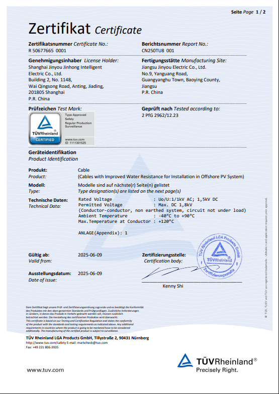
Where a certificate is part of that set, we expect you to verify it with the body that issued it rather than take the paper at face value. That is the practice buyers are told to follow, and a supplier who resists it is telling you something.
If Something Is Wrong
If a delivered length does not match the construction on the approved drawing, we rework or remake it against that same drawing. The drawing is the acceptance criterion for both of us, which is why we spend the quotation stage getting it exact rather than fast.
DOC. 01
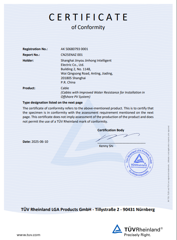
🔍 ENLARGE
DOC. 02
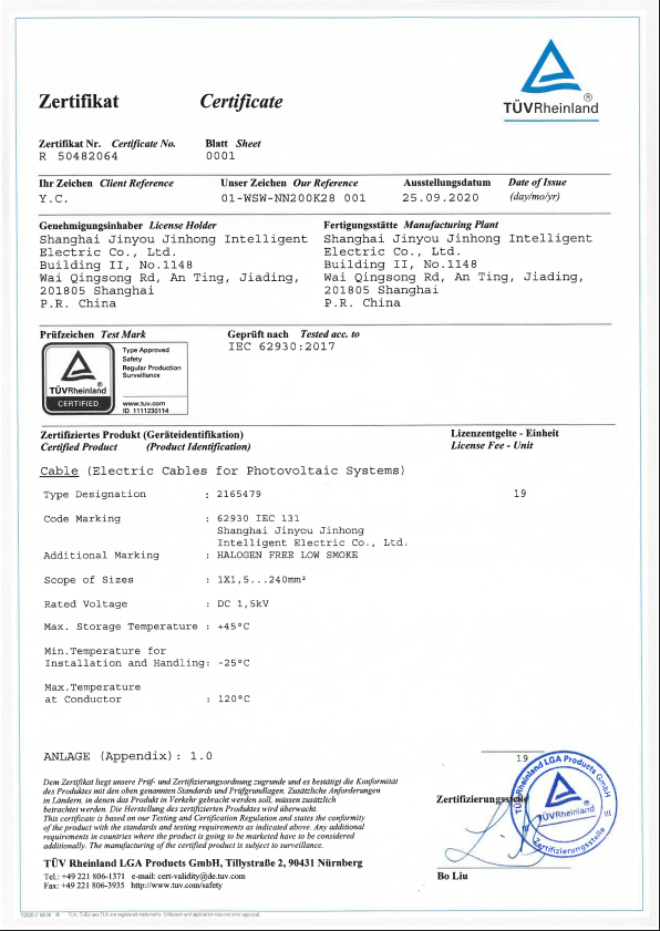
🔍 ENLARGE
DOC. 03
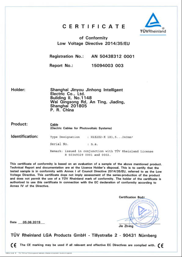
🔍 ENLARGE
DOC. 04
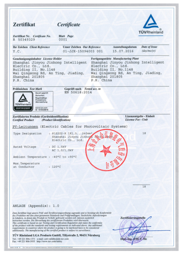
🔍 ENLARGE
DOC. 05
🔍 ENLARGE
DOC. 06
🔍 ENLARGE
DOC. 07
🔍 ENLARGE
×
From Enquiry to Released Drawing
Enquiry and NDA
— a mutual non-disclosure agreement is signed before your drawings are opened, and your bill of materials is not shared with third parties.
Construction Review
— a cable engineer reads the drawing, sample or part number and lists anything that is ambiguous, missing or physically inconsistent, at no charge.
Written Quotation
— returned within 24 hours, stating the construction we will build, the lead time and the commercial terms.
Sample and Approval
— a sample length in 2–3 weeks; the approved sample and the drawing together become the released specification.
Production Against the Released Drawing
— we build to that document. If a length leaves our line outside it, that is ours to rework or remake.
Marking, Packing and Despatch
— drum and box marking carries the manufacturer, the country of manufacture and the cable type so the goods can be identified without opening the packaging.
What a Quotable Enquiry Carries
| Field | What to Specify | Why It Changes the Answer |
|---|---|---|
| Duty | Power, control, signal or heat-generating; fixed, moving or thermally exposed | Sets the family before any dimension is discussed |
| Cores and cross-section | Core count, cross-section in mm² or AWG, and pair or triad grouping | Drives copper content, which drives price and diameter |
| Voltage and temperature | Rated voltage class and the real ambient and conductor temperatures | Selects the insulation system and the temperature classification code |
| Screen requirement | Individual pair screen, overall screen, both, or none; drain wire required or not | Decides whether a 360-degree gland termination is possible at your end |
| Earthing or grounding philosophy | Screens earthed at one end or both, and at which end | Changes the screen construction we recommend, not just the installation drawing |
| Flame and smoke requirement | The flame test part and category letter your specification names | A bare series number without a category letter is not a specification |
| Standards regime | Whether the installation is written to IEC, GB, or a North American wiring code | Where a listed or labelled construction is required, that requirement has to be on the enquiry |
| Quantity, cut length and drum | Metres per type, cut lengths and the drum length you want | Sets setup cost, packing and whether the order is stocked or made to order |
Industrial Cable Engineering Tools & Calculators
Cable Duty-Class Selector
Two answers narrow an industrial cable enquiry to one family and the construction questions that decide it. Axis A is what the cable carries electrically. Axis B is what happens to it mechanically once it is installed. Nothing is sent anywhere and no contact details are asked for.
Use ToolThermocouple Compensating-Wire Loop Resistance Calculator
A thermocouple loop has no supply of its own, so its total resistance is a design constraint rather than a detail. This calculator returns the loop resistance of a run and compares it against the maximum external resistance your instrument is specified for. The whole calculation is Ohm’s law on a there-and-back conductor pair; it stays in your browser.
Use ToolHeat-Tracing Circuit Length and Load Estimator
Self-regulating tape is bought by the metre and installed as a circuit, and the circuit is what runs out first. This estimator returns the steady-state load of a circuit and the longest circuit a given breaker will carry, so a pipe run can be split into the right number of circuits before a construction is worth discussing.
Use ToolIndustrial and Special Cable FAQ
What is an instrumentation cable?
An instrumentation cable carries a measurement rather than power, so its job is to deliver the signal without letting the plant’s electrical noise change it. That is why the construction is built around twisted pairs, screen layering and published capacitance and inductance limits rather than around ampacity.
On our screened pair constructions the published limits are working capacitance ≤90 pF/m, capacitance unbalance ≤1 pF/m and distributed inductance ≤0.6 µH/m at 1 kHz.
On our screened pair constructions the published limits are working capacitance ≤90 pF/m, capacitance unbalance ≤1 pF/m and distributed inductance ≤0.6 µH/m at 1 kHz.
What is the difference between an instrumentation cable and a control cable?
A control cable switches or enables something and carries no load current; an instrumentation cable carries a measurement whose accuracy is the deliverable. The practical consequence is screening discipline: a control core can tolerate interference that would put a 4–20 mA loop out of specification.
Instrumentation cable types are described by pair count and screen arrangement; control cable types by core count and cross-section. In the Duty-Class Method above, control and signal are two separate Axis A classes for exactly this reason.
Instrumentation cable types are described by pair count and screen arrangement; control cable types by core count and cross-section. In the Duty-Class Method above, control and signal are two separate Axis A classes for exactly this reason.
What is a VFD cable, and is your VFD cable the motor feeder?
Ours is the drive’s control-circuit cable, not the drive-to-motor power feeder. The BPKX range is built for the weak voltage and current signals in the control circuit of a variable frequency drive, at 1 to 20 cores and 0.75 to 2.5 mm².
The distinction matters because the two follow opposite earthing rules. A drive power feeder is normally terminated at both ends, at the cabinet and at the motor; a low-frequency analogue instrumentation screen is normally earthed at one end only.
VFD cable termination is where a lot of the benefit is won or lost, which is why the screen construction we quote is dependent upon the gland you plan to use.
The distinction matters because the two follow opposite earthing rules. A drive power feeder is normally terminated at both ends, at the cabinet and at the motor; a low-frequency analogue instrumentation screen is normally earthed at one end only.
VFD cable termination is where a lot of the benefit is won or lost, which is why the screen construction we quote is dependent upon the gland you plan to use.
What type of cable is used for VFDs
A VFD cable is not one product. A drive installation typically needs two: the drive-to-motor feeder is a screened power cable built to handle voltage spikes and common-mode current, while the control circuit needs a screened control cable that keeps the low-level signals clean in the same enclosure.
We build the second of those two. If your enquiry is for the motor feeder, say so and we will tell you plainly that it is outside this range.
We build the second of those two. If your enquiry is for the motor feeder, say so and we will tell you plainly that it is outside this range.
Do VFDs need special cable
The honest answer is that it depends on run length, how close the signal wiring runs to the drive output, and whether the drive shares an enclosure with the controls. Shielded cable feels like an expensive precaution until the second drive goes in. An unshielded run works fine until the run gets longer or another drive is added.
The decision usually gets made after the machine is wired, when the noise shows up, which is the most expensive moment to make it. The common objection is that drive-rated cable is expensive, inflexible and slower to install, and one industry estimate quoted by Hallam-ICS from Belden puts adoption at fewer than 20 per cent of the applications that should be using it.
That is the opposite of the assumption most buyers arrive with, which is that specifying it is gold-plating.
The decision usually gets made after the machine is wired, when the noise shows up, which is the most expensive moment to make it. The common objection is that drive-rated cable is expensive, inflexible and slower to install, and one industry estimate quoted by Hallam-ICS from Belden puts adoption at fewer than 20 per cent of the applications that should be using it.
That is the opposite of the assumption most buyers arrive with, which is that specifying it is gold-plating.
What is a robot cable
A robot cable is built for a conductor that will be bent, twisted or dragged for the working life of the machine, rather than laid once. The construction differences are finer stranding, shorter lay lengths, an abrasion-resistant sheath and a screen built to move without fretting.
Our YY and RO-F families are halogen-free, plasticiser-free and heavy-metal-free, at 2 to 20 cores and 0.14 to 6 mm².
Our YY and RO-F families are halogen-free, plasticiser-free and heavy-metal-free, at 2 to 20 cores and 0.14 to 6 mm².
What type of cable is used for heat tracing
Self-regulating tape is the common answer for freeze protection and temperature maintenance, because the conductive polymer between the two bus conductors passes more current as it cools and less as it warms. That is why it can be cut to length on site and why overlapping it does not create a hot spot.
For long metal pipelines the answer changes to a skin-effect system, where our single-circuit runs cover 200 m to 10 km at 15 to 270 W/m.
For long metal pipelines the answer changes to a skin-effect system, where our single-circuit runs cover 200 m to 10 km at 15 to 270 W/m.
Screen earthing at one end or both ends
Neither is universally right, and a supplier who tells you otherwise is simplifying. For low-frequency analogue signals, earthing at one end breaks the loop that a ground-potential difference would otherwise drive through the screen. For high-frequency interference, bonding both ends gives the screen a low-impedance path and better immunity.
Tell us the earthing philosophy on the project and we will build the screen and drain-wire arrangement that lets your installer execute it.
Tell us the earthing philosophy on the project and we will build the screen and drain-wire arrangement that lets your installer execute it.
Minimum bend radius for instrumentation cable
We publish an installed bend radius of not less than 6 times the cable outer diameter for unarmoured and braid-screened constructions, and not less than 12 times for armoured or copper-tape screened constructions.
Those are the final installed figures, not pulling radii. Published installation practice uses a larger radius while the cable is being drawn in, so plan the pull around that rather than around the installed number.
Those are the final installed figures, not pulling radii. Published installation practice uses a larger radius while the cable is being drawn in, so plan the pull around that rather than around the installed number.
Thermocouple extension cable versus compensating cable
An extension cable uses conductors of the same nominal composition as the thermocouple and carries an X suffix; a compensating cable uses a different, cheaper alloy pair that matches the e.m.f. over a limited range and carries a C suffix. Our range covers both, across SC, RC, KC, KX, NC, NX, EX, JX and TX.
IEC 60584-3 governs the identification and manufacturing tolerances for both, expressed against the e.m.f. versus temperature relationship of IEC 60584-1. Mineral insulated extension and compensating cables are outside that standard’s scope.
IEC 60584-3 governs the identification and manufacturing tolerances for both, expressed against the e.m.f. versus temperature relationship of IEC 60584-1. Mineral insulated extension and compensating cables are outside that standard’s scope.
Flame retardant and fire resistant grades
Flame-retardant constructions carry the ZR prefix and fire-resistant constructions the NH prefix, with the low-smoke halogen-free series coded WD in grades ZA, ZB and ZC. Tell us the flame test part and the category letter your specification names, because the category letter is the severity and a bare series number does not specify anything.
The two regimes line up part for part. For the bunched-cable Category C test, China’s national standards platform records GB/T 18380.35-2022 as identically adopting IEC 60332-3-24:2018, so a specification written to either one is answerable against the other.
One wording note we hold to: fluoroplastic insulated constructions are not described here as halogen-free, because the halogen acid gas test excludes hydrofluoric acid.
The two regimes line up part for part. For the bunched-cable Category C test, China’s national standards platform records GB/T 18380.35-2022 as identically adopting IEC 60332-3-24:2018, so a specification written to either one is answerable against the other.
One wording note we hold to: fluoroplastic insulated constructions are not described here as halogen-free, because the halogen acid gas test excludes hydrofluoric acid.
Minimum order quantity and sample policy
Stocked constructions carry no minimum. A made-to-order construction starts at 100–200 m per type, and samples of a stocked construction are free while a custom construction is sampled against a sample charge and an approved construction drawing.
Urgent orders on a stocked construction can ship in about one week; feasibility for a made-to-order construction is confirmed at drawing review.
Urgent orders on a stocked construction can ship in about one week; feasibility for a made-to-order construction is confirmed at drawing review.
How to verify what you receive
Weigh the drum and check the conductor. Copper is heavy, and conductor substitution is the failure mode buyers are most often warned about, so a reel that feels light for its length is telling you something before any instrument does.
Beyond that, ask us for the construction on the released drawing and measure against it. Where a certificate forms part of your document set, verify it with the body that issued it rather than accepting the paper.
Beyond that, ask us for the construction on the released drawing and measure against it. Where a certificate forms part of your document set, verify it with the body that issued it rather than accepting the paper.