Offshore Photovoltaic Cable: 2026 Buyer’s Guide to Route Duty
Industrial renewable-energy guide · Updated September 2026
Offshore Photovoltaic Cable refers to a route-duty question for this guide rather than a complete product-selection decision. First, map out the segments of each route, what can move, what can get wet, which interfaces it crosses, and what record will show acceptable installation before energization. This method brings more value to an RFQ and prevents a catalog label from being seen as a project decision.
“Offshore” describes very different installed duties. It can refer to a protected floating array, a coastal route with a shore transition, or an exposed marine-influenced installation. The available floating-photovoltaic evidence doesn’t make these settings interchangeable. This guide is then a decision framework for developers, engineering, and procurement teams. Searches for “offshore photovoltaic cable price,” “offshore photovoltaic cable for sale,” or “offshore photovoltaic cable for solar panels” signal different procurement questions; this guide does not compare prices or sellers, but helps a buyer define the route-duty evidence needed before a component or custom-solution discussion and clearly record the intended handover-stage approval owner in the same evidence grid. It isn’t a model list, price guide, supplier ranking, or substitute for the electrical, marine, and installation reviews required for a project.
Start with the route and its evidence owners. Let the product conversation follow the route facts.
Define the Route Environment Before You Name a Cable
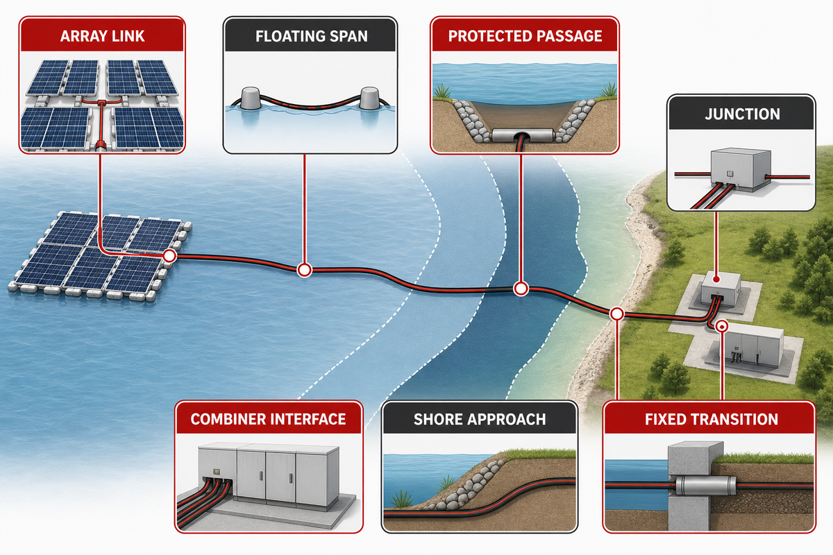
Start with a drawing, not a product name. Divide the electrical route into the segments that are important to the project: array-to-array connections, spans between floating units, protected passages, junctions, combiner interfaces, shore approaches, and any transition into fixed infrastructure. For each segment, determine if it’s dry, intermittently wet, protected from direct movement, subject to movement, accessible for inspection, or subject to a change in support condition. Before an RFQ is released, record those distinctions in the route worksheet with the buyer, supplier, and approval owner named beside the segment. The risk is an ambiguous hand-off: a supplier can quote only the duty described, while an inspector must verify the duty actually installed.
This classification addresses a frequently occurring scope error. A finding from a specific floating configuration may be applicable and informative without showing class suitability for more severe exposure conditions. For example, a 2026 mechanical-response study of an overhead cable in an offshore floating-PV configuration examines coupled wind, wave, current, mooring and span conditions; its value here is the route-specific method, not a universal cable rating.
Route question
Evidence to obtain
Decision owner
Where does this segment physically run?
Approved route drawing and segment identifier
Electrical and layout design leads
What exposure is credible?
Site/environment classification and interface description
Project engineering lead
Can the segment move or lose support?
Support arrangement, span record and movement-review trigger
Mechanical/marine coordination lead
How will it be inspected or recovered?
Access plan, location marking and ownership record
Construction and operations leads
Don’t constrain a project to a false dichotomy of “onshore” or “offshore.” Rather, the issue is whether the evidence supplied for each segment matches the duty expected there.
Build the Route-Duty Evidence Grid Before Comparing Products
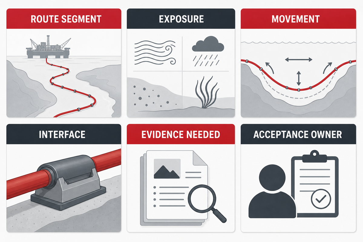
The primary output is a Route-Duty Evidence Grid. It converts a vague request for a “marine grade” cable into a common understanding for design, procurement, construction and quality assurance. A supplier will now be able to respond to the conditions identified in the grid rather than speculate on what ‘offshore’ may mean for a given project.
Grid field
What it captures
Why it matters
Route segment
A traceable drawing reference
Keeps evidence tied to a real location.
Credible exposure
Wet, protected, water-adjacent or marine-influenced condition
Separates the route question from a broad material label.
Movement and support condition
Static, moving, span-controlled or support-dependent
Creates an escalation path for mechanical review.
Interfaces
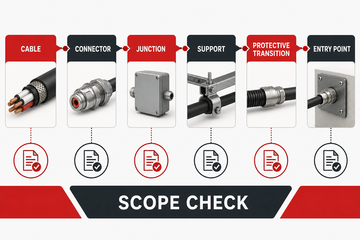
Terminations, connectors, enclosures, supports and protection transitions
Stops the cable jacket from becoming the only item reviewed.
Evidence needed
Data sheet, test scope, drawing, installation instruction, inspection or test record
Shows what document can answer which question.
Owner and acceptance record
Named reviewer, hold point and handover record
Prevents a document bundle with no acceptance decision.
The evidence grid isn’t a compliance certificate. Rather, it identifies gaps in the evidence before material, installation or energization decisions are made. Where a condition can’t be articulated in the evidence grid, it has very likely not been articulated clearly enough for a request for proposal.
Use project vocabulary as a scope check
The vocabulary associated with search language is problematic to the clarity of project boundaries. A client may say things like solar power, solar panels, FPV, offshore floating solar, floating solar power, floating photovoltaic power, floating solar farm, solar power plant. Internally, those terms may be referring to a reservoir, other water bodies, a coastal project, or one of several floating solar systems. They don’t answer if the route involves a marine environment, a marine environmental problem, corrosion, biofouling, marine organisms, or a protected inland environment.
Vocabulary group
Terms a project may use
Scope question to resolve
System layout
floating platform, floating panels, floating modules, photovoltaic arrays, solar arrays, cable system, PV system, power conversion
Does a cited document apply to this product, installation and system boundary?
Buyer context
solar installations, power plants, clean energy, green energy, sustainable energy, energy transition, low-carbon
Is this a project objective or an evidence-backed cable decision?
Limit your use of language in the RFQ to cases in which it clarifies the scope of the work. For example, a review of floating photovoltaic installations may discuss power generation at a broad level, while a cable-route decision still needs the applicable interface, support and exposure record. If a project is using finite element analysis or another mechanical method, record its model boundary and inputs rather than implying that one analysis validates every floating offshore route.
Map Cable Decisions Across the Floating-PV Architecture
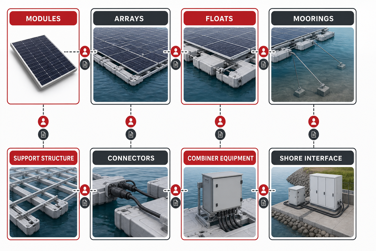
The cable route is a component of an integrated system: modules and arrays, floats, frames, anchors or moorings, support structure, connectors, combiner equipment, conversion equipment, shore interfaces, and protective systems. Different sections may be owned by different teams, but the buyer should delineate the system interfaces rather than ask one product document to take on every responsibility. A project procurement review should identify the interface owner, the supplier document that covers the interface, and the engineer who accepts a route change. This avoids a coordination gap in which a product document is treated as proof of an entire system interface.
A floating-system patent may describe how grids, floats, frames, and coupling elements create interfaces; it cannot prove field performance or suitability. Use architectural sketches in a similarly bounded way: they may show where an interface needs ownership, but cannot determine the final design.
For each route segment, identify the party that controls that segment and the party that approves a change in routing.
For each connector, enclosure and transition, identify the party responsible for compatibility.
For each cable application, identify the owner of the electrical design for bonding, grounding, fault interruption, arc-fault protection, lightning protection, and emergency-isolation coordination where applicable.
Identify the records that must be in place before the route is permitted to be energized.
Those are coordination questions, not universal design instructions. The appropriate electrical designer and project requirements determine which protective functions apply.
Separate Movement Duty from Environmental Exposure, Then Reconnect the Failure Chain
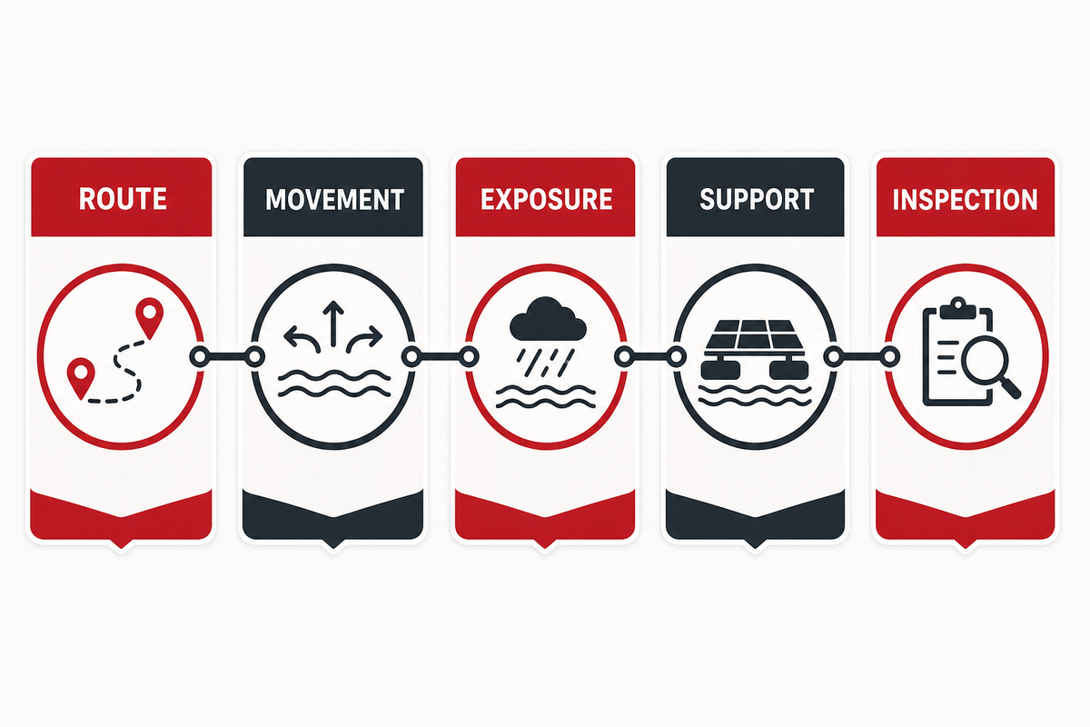
Exposure and movement must have separate evidence tracks. A segment, for example, may be mechanically quiet, but may become wet many times. Another may be constantly above water, but may experience movement, a changing span, or a support condition that needs review. The 2026 mechanical response study is useful because it treats cable response as dependent on configuration and coupled loads. It shouldn’t be used to determine a fatigue life of another routing option.
Separate tracks don’t necessarily equate to distinct failure modes. A support that loses its holding ability or is incorrectly installed may change movement duty and should be reviewed. For this reason, the grid requires the support-condition field and the inspection/access field. During procurement, the buyer should ask the supplier and the responsible engineer to record whether a support condition has changed before the segment is accepted. The risk is that a route can pass a catalogue comparison while the installed support creates a different movement duty.
Static-versus-Movement Route Escalation: if a segment has credible platform motion, changing geometry, a long or unsupported span, uncertain support retention, or a reported route change, move it from catalogue comparison into the project’s mechanical and electrical review path. Record the decision and the responsible owner.
Review Cable, Connector, Junction, and Protection as One Exposure Chain
The cable is but one feature of the route. Consider cable segments, terminations, connectors, enclosures, supports, protective transitions and physical entry points. The issue isn’t whether a component has a test statement. The issue is whether that statement describes the component, revision, installed interface and the route condition being proposed. At the procurement review, ask the supplier and inspector to cross-reference the product revision, connector interface, and route segment in the test record. The risk is a mismatch: a valid component document can fail to answer whether the installed chain was assembled and protected as reviewed.
Bounded water-exposure data show the relevance. A 2024 photovoltaic-cable study tested two insulations in freshwater and artificial seawater. The data are useful for examining exposure conditions, but they shouldn’t rank materials for a marine route, predict lifetime, or provide design approval.
Ask for compatible-interface and workmanship evidence
For each chain element, request the cable interface, the installation guide, the qualified person/method for the installation, the inspection/hold-point log, and the log of deviations. Good cable claims cannot correct an incompatible connector, a poorly controlled field assembly, an unprotected abrasion point or an unrecorded deviation.
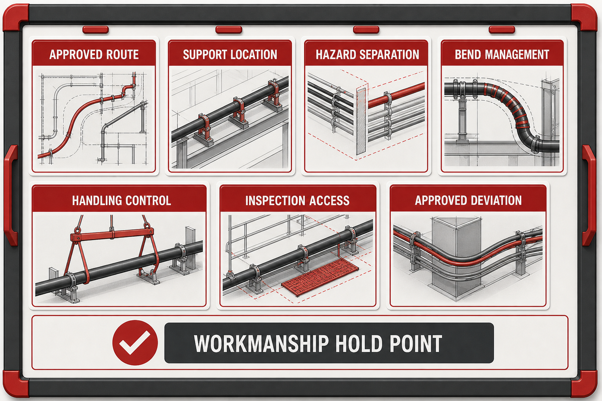
Close Installation Controls Before Delivery
The route should be installable as drawn. Prior to delivery, confirm the agreed upon route, location of supports, the separation from hazards, bend-management locations, handling controls, transitions to protection, identification scheme, the means of access for inspections and deviations, and the authority to deviate. Add workmanship hold points for installation steps where a subsequent visual inspection cannot confirm how the method was performed. Before delivery, the buyer, installation contractor, and inspector should confirm that route records and approved deviations are available at the work front. The practical risk is rework: a support or protection change can become difficult to verify after access is restricted.
The 2021 review of floating-PV installation and maintenance issues provides useful context here. While access, wind, movement, and commissioning may affect cables, it does not provide a general method statement for installation. Use this document to develop project-specific controls, particularly where access changes after installation of the array.
Hold the approved route and segment identifiers before installation is carried out.
Record the actual protection and support installed, including any approved change.
Keep a record of the connector/interface field assembly and the route record for connector/interface compatibility.
Confirm access for future inspection, safe fault response and, where relevant, recovery after a failure or at decommissioning.
Escalate bends, abrasion evidence, damaged protection, unexpected slack or changed movement conditions through the agreed owner.
Keep units in the route record, not in a generic promise
Units provide an auditable evidence record, but the approved drawing and project calculation supply the actual values. The examples that follow show how a handover form can preserve units without becoming a design recommendation.
Record category
Example notation on a project form
Control purpose
Route segment
10 m segment and 2 m support spacing
Links the drawing reference to a visible span.
Protection transition
4 mm documented edge detail and 30 cm protected clearance
Preserves the condition actually reviewed.
Bend and access
45° routing datum and 1.5 m access reference
Lets a later inspection locate the intended geometry.
Circuit label
1,000 V and 10 A only where the approved schedule uses those values
Separates a project circuit record from a cable marketing statement.
Connected equipment
5 kW and 50 Hz only where the equipment data record applies
Identifies the applicable system interface.
Inspection event
20 min check duration and 24 h recheck record where required
Records what was done without prescribing a universal interval.
Deviation closeout
2 days to close a documented issue and 100% retained photo set
Keeps an exception visible until an owner closes it.
Document control
12 months or 1 year only if the project retention plan specifies it
Connects record retention to the project’s own rule set.
Environmental observation
15°C observation entry and 80% condition field only when actually measured
Stops a narrative note from losing its measurement context.
Commission with an Energization Evidence Pack, Not a Compliance Slogan
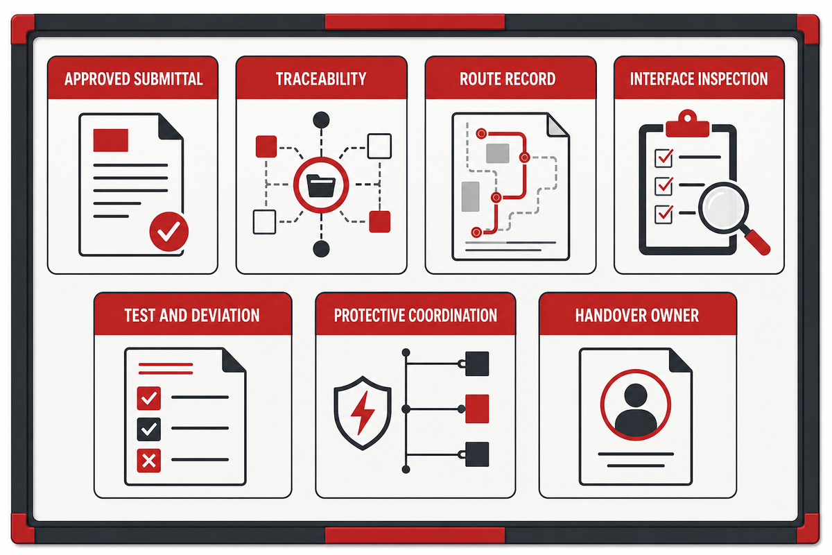
Prior to energization, capture an Energization Evidence Pack. Commissioning appears among the work-safety topics in a 2021 floating-PV installation and maintenance review, but the source does not define a universal acceptance pack. This distinguishes a product certificate from a project acceptance decision and gives the handover team a means to locate the evidence later. The handover reviewer should require the buyer, supplier, and inspector to use the same document revision and segment identifier before energization. That reduces the risk of a missing record or an unverified deviation being carried into operations.
Evidence-pack item
Question it answers
Approved submittal and revision
Which product and documentation version was accepted for this scope?
Traceability and delivery record
Can the installed material be linked to the accepted evidence?
As-built route record
Where is the route, and what changed from the approved drawing?
Interface and workmanship inspection
Were connectors, enclosures, supports and protection transitions checked?
Test and deviation record
What was tested, what was accepted, and who approved exceptions?
Protective-function coordination record
Who verified the applicable project electrical-protection interfaces?
Handover owner
Who receives the evidence and controls post-handover changes?
This checklist does not certify a project. However, its purpose is not merely to allow acceptance criteria to be checked; it makes the acceptance route inspectable and allows a missing owner to be identified before the system is energized.
Plan Inspection and Fault Response Around Accessible Evidence
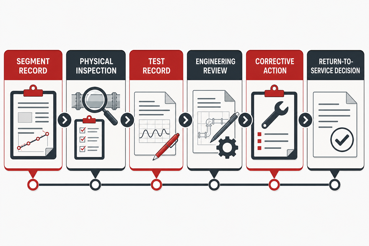
After project handover, operations teams require records containing segment identification, photographs of the project route, location references, approved deviations, interface findings, support condition, maintenance records and decisions on corrective action. Describe inspection triggers instead of implying that one rigid inspection interval applies universally. Useful inspection triggers may include abnormal movement, visible slack, damaged protection, an altered route, water-exposure concerns, a connector finding, or an electrical anomaly.
Although monitoring is an essential input, the project team should define when it can support inspection or fault diagnosis. When a fault decision relies on physical inspection, the project’s electrical-safety owner should define the inspection, tests, records, and controls required before return to service. For operations, the asset owner should define when an inspector, supplier, or electrical engineer must review the record before a corrective action is closed. This prevents a fault response from being reduced to a monitoring alert with no physical evidence.
Operations escalation matrix: define the observed condition, affected segment, immediate safe-state action, required inspection or test, record location, corrective-action approver and closeout condition. This is more useful than a generic statement that a route is “maintenance-free.”
Use Standards and Supplier Documents for Scope Checks
Standards, recommended practices, certificates, data sheets and test reports may play different roles. Some can frame a broader lifecycle system when their stated applicability matches the project; others describe one component, one product revision or one test condition, so treat them as scope-specific evidence, not slogans.
Published fields still need a route decision. The fields below are examples of what a buyer may encounter in a photovoltaic power-system cable reference. They identify fields to reconcile during a request; they do not establish blanket approval for a floating or marine-influenced installation.
Published field
Value to verify
Scope check before acceptance
Operating-temperature range
Supplier-stated value
Confirm the stated boundary against the installed route and exposure record.
Maximum conductor temperature
Supplier-stated value
Confirm the applicable circuit and operating condition.
Rated system voltage
Supplier-stated value
Confirm the approved circuit schedule.
Alternative rated system voltage
Supplier-stated value
Confirm which published option is actually offered for the request.
AC test voltage
Supplier-stated value
Read the test boundary and revision, not only the headline value.
Short-circuit temperature
Supplier-stated value
Confirm whether the project protection study uses the same condition.
Conductor cross section
Supplier-stated value
Confirm the offered size and the route-specific calculation.
Minimum bending radius
Supplier-stated value
Confirm the drawing, support arrangement and installation detail.
Offshore-PV listed core range
Supplier-stated value
Confirm the exact designation and stated product boundary.
Referenced test standard
Supplier-stated reference
Confirm the edition and the part relevant to the requested route.
Waterproof connector operating range
Supplier-stated value
Confirm the connector, contact configuration and offered product boundary.
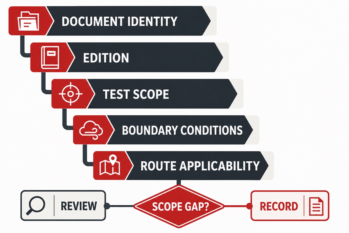
For every document, request its identity and edition, product or system scope, test condition, limitations, traceability link, intended route applicability and the project reviewer who decides whether the document is sufficient. Where an offshore or exposed-marine condition is being considered, ask explicitly whether the evidence addresses that condition or only a different floating-PV setting. During an RFQ review, the buyer and supplier should map each document to the route segment and identify any scope gap before using it as an acceptance record. The risk is an ambiguous claim of compliance when the test boundary does not match the installed interface.
When you complete the Route-Duty Evidence Grid, a team looking for a project configuration discussion can refer to Jinyou’s offshore photovoltaic cable solution page. That page is the location for a product and custom-solution discussion. This discussion does not establish a product rating, certificate, test result, plant capacity, project outcome, export count, or performance claim. This guide is the buyer’s evidence framework.
What the 2025–2026 Floating-PV Context Means for Buyers
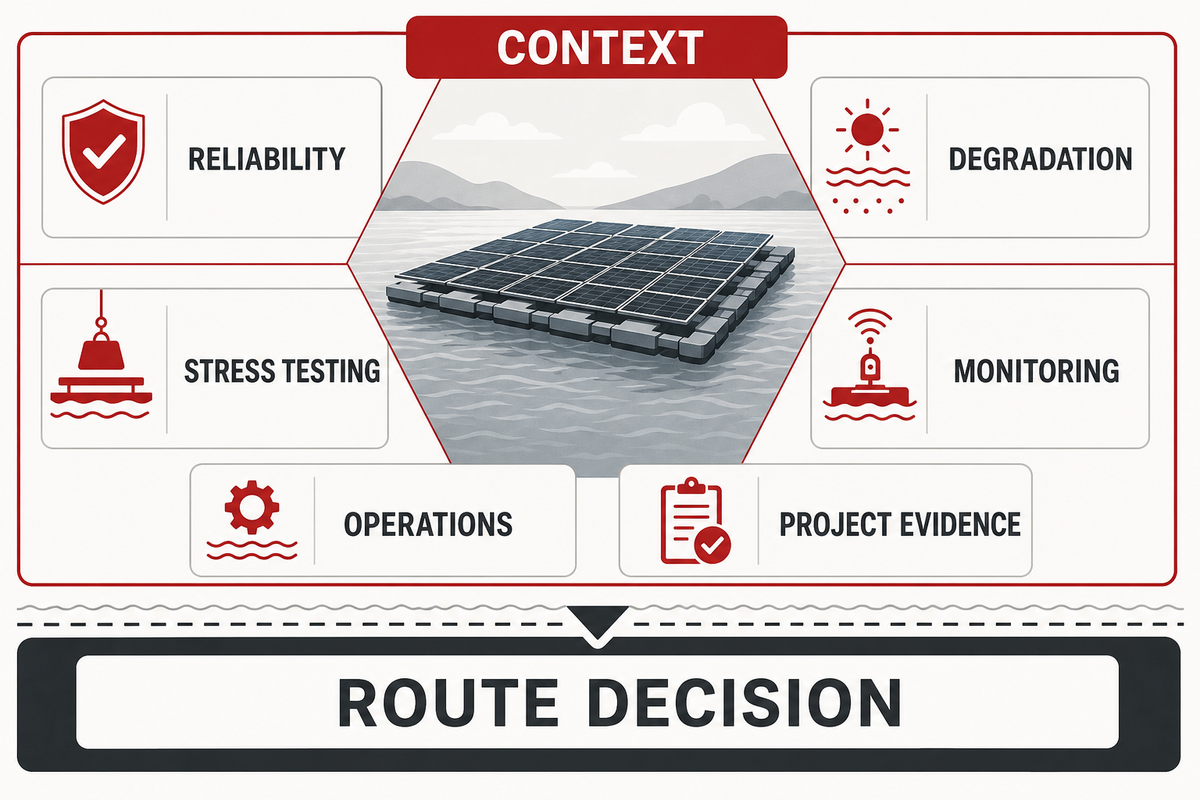
Recent work on floating PV demonstrates the importance of discipline in the evidence presentation over a market forecast. The IEA PVPS’s 2025 public review indicates that there are several unresolved issues related to reliability, degradation, stress testing, monitoring, and the operation of floating systems. The buyer implication is modest but important: keep route decisions, evidence owners and handover records visible instead of importing assumptions from a fixed ground-mounted array.
At a system level, a feasibility study on hybrid offshore wind-and-floating-PV treats export-cable capacity as a modeling constraint. That is not a local photovoltaic-cable construction rule; it is another reason to keep system-capacity questions separate from route-level component and installation decisions.
Thus, the important question during the procurement process isn’t which label is optimal. For a procurement team, the practical consequence is to assign the supplier, engineering reviewer, and handover owner before a purchase order turns broad context into a route-specific commitment. That avoids a gap between a system-level feasibility statement and a local installation or acceptance decision. The critical question is which evidence shows that the route, interfaces, and handover controls have been assessed for the project’s stated condition.
Frequently Asked Questions
What is a photovoltaic cable?
A photovoltaic cable carries electrical energy between relevant components of a photovoltaic system. For a floating or marine-influenced project, that broad function is only the starting point. The buyer still needs route, voltage, interface, movement, exposure, installation and acceptance information before deciding whether evidence applies to a particular segment. The final decision also depends on the accepted system architecture and the project’s electrical safety responsibilities.
How are offshore solar cables different from onshore ones?
The important difference is installed duty, not a marketing word. A water-adjacent or floating route can introduce movement, support, access, abrasion, wet exposure and interface questions that differ from a fixed land route. Don’t assume that all floating, coastal and exposed-marine routes are alike; classify the actual segment and request evidence against that condition. A route can be mechanically quiet yet wet, or dry yet dependent on a support arrangement that needs separate review.
What evidence should I request before buying offshore photovoltaic cable?
Request a route map, segment environment and movement information, product identity and revision, document/test scope, installation instructions, traceability, connector and interface evidence, support/protection details, deviation process and energization-acceptance records. Ask the project team to name the reviewer and acceptance owner for each item. If a supplier response names a standard or a test, ask which product revision and route condition it actually covers, and what remains for the project team to verify.
Can a standard photovoltaic cable be used on a floating solar project?
That can’t be decided from the generic label alone. Classify the route, identify exposure and movement, map interfaces and supports, then compare the applicable evidence with the project’s stated condition. The responsible engineering and acceptance teams decide whether the documented evidence is sufficient for the intended use. They should also confirm whether access, inspection, protective-function coordination and future recovery responsibilities are addressed for the installed route.
How do I prepare an RFQ for an offshore photovoltaic cable solution?
Provide system architecture, route drawings, segment environments, expected movement or support conditions, circuit information, connector and termination interfaces, installation constraints, documentation needs, traceability requirements and the acceptance process. State which items need project-specific confirmation instead of asking a supplier to infer them from the word “offshore.” A useful RFQ also names the expected handover records and the party who can approve a deviation.
This article is an educational framework. It does not provide a universal offshore design, an acceptance certification, product-performance guarantee, market forecast or service-life promise.
ENGINEERING CONTEXT
Cable guidance backed by manufacturing focus
Shanghai Jinyou Jinhong Intelligent Electric Co., Ltd. has focused on new energy cable manufacturing since 2006, supporting solar/PV, energy storage, EV charging, and industrial or special-cable applications.
Use this guidance to prepare a clearer engineering or procurement discussion: operating environment, conductor and insulation expectations, route length, voltage, installation method, and project schedule.
Certificate evidence should be matched to the construction being specified. Public certificate evidence applies to H1Z2Z2-K solar cable constructions and should not be read as blanket certification for every JINYOU Cable product family.
PROJECT BRIEF
Move from article to specification
Share the application, required cable family, target standard, quantity range, and delivery window. The team can help structure the next engineering and procurement conversation.