An EV DC charging cable is a flexible high-power connection between a DC charging unit and a vehicle inlet. Validating it means linking the declared duty profile to the exact conductors, contacts, terminations, sensors, thermal-management state, control response and test record. Connector naming or a peak-current label cannot prove that the complete heat chain is controlled.
Bottom line: compare cable systems only after you freeze the thermal assumptions, identify which standard governs each object, replay the intended current-versus-time duty and preserve results from the same physical and software configuration.
Summary: A Practical Validation Path
Define the approval boundary: The cable, coupler, inlet, EVSE and adapter are related but distinct components.
Relate each standard to the object and decision it actually governs.
Freeze six thermal variables prior to comparing current or temperature results.
Choose among passive, temperature-controlled and actively cooled architectures by duty and failure response—not charger power alone.
Replay the declared duty, instrument the heat chain between the cable and contact and retain one configuration-consistent evidence packet.
This guide is deliberately narrower than a general EV charging cable guide. It doesn’t cover basics of AC vs. DC, routine inspections or model selection. This guide focuses on the integration of standards, thermal assessment, duty replay and test traceability, and how these affect an engineering release.
Consumer searches for Type 1, Type 2, a Type 2 charging cable, J1772, Level 1, Level 2, home charger, portable EV charger, charging point or EV charging station describe AC charging. They are outside this DC fast charging scope; electric car and Nissan Leaf compatibility are interface questions, not ampacity evidence.
What Is an EV DC Charging Cable?
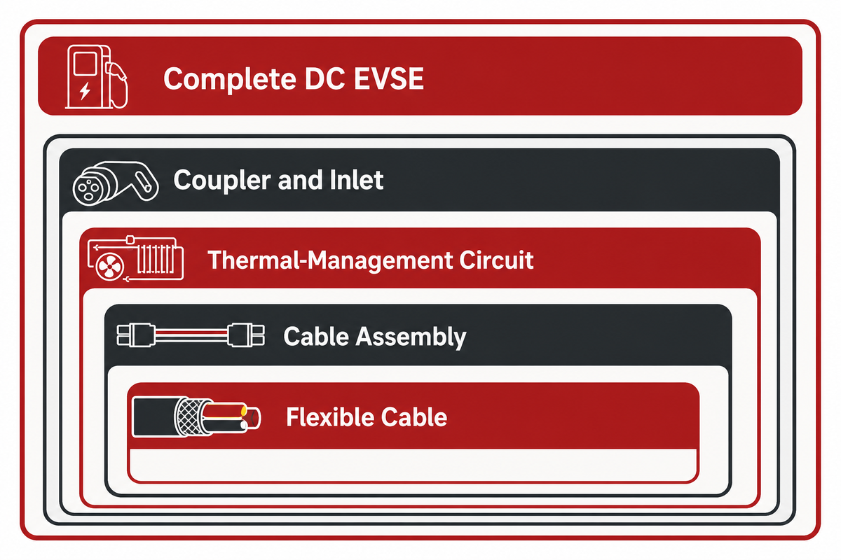
An EV DC charging cable is a flexible cable assembly that connects a DC charging station to a vehicle interface. The practical validation boundary includes the insulated power and protective conductors, signal elements, both terminations, connector contacts and any sensors or coolant paths that influence current control.
That boundary is easy to blur. An in-vehicle high-voltage cable is exposed to a different installation environment. A detachable AC cord does not represent a tethered Mode 4 DC assembly. The vehicle inlet and mating coupler form the interface while the complete EVSE contains power conversion, protection, and control systems and integrated communication and control functions. Evidence of approval for one component should not be extended to the others.
Use a five-object boundary map
Object
Typical contents
Decision supported
What remains separate
Flexible cable
Power, protective and signal conductors; insulation; jacket
Construction and cable test scope
Coupler and EVSE performance
Cable assembly
Cable plus terminations, contacts and strain relief
Assembly heat path and mechanical integrity
Vehicle inlet and station controls
Thermal-management circuit
Coolant lines, fittings, pump interface and sensors
Heat removal and fault response
Uncooled fallback behavior
Coupler and inlet
Mating geometry, contacts, locking and interface functions
Physical and electrical interface compatibility
Cable ampacity and site commissioning
Complete DC EVSE
Power stage, protection, communication and controller
System-level charging behavior
Vehicle-side approval
Each boundary should have an owner. The construction and termination of the cable is controlled by the cable engineer. The connector contact and housing is controlled by the connector owner. The sensing, derating, and shutdown functions are controlled by the integration and controls team.
Evidence note: The official IECEE abstract for IEC 62893-1:2017 places flexible charging cables between the charging-station supply point and the EV and covers rated voltages up to 1,500 V DC. That public abstract defines a cable object, not a complete charger; confirm the project’s selected edition and amendments in the current IEC catalogue.
Map Each Standard to the Object It Governs
Standards lists become useful only when each document is tied to its governed object, supported decision and explicit limit. Different questions are asked regarding cable construction and thermal management, coupler compatibility and a complete EVSE’s safety. Treating multiple standard numbers as one universal approval creates an evidence gap.
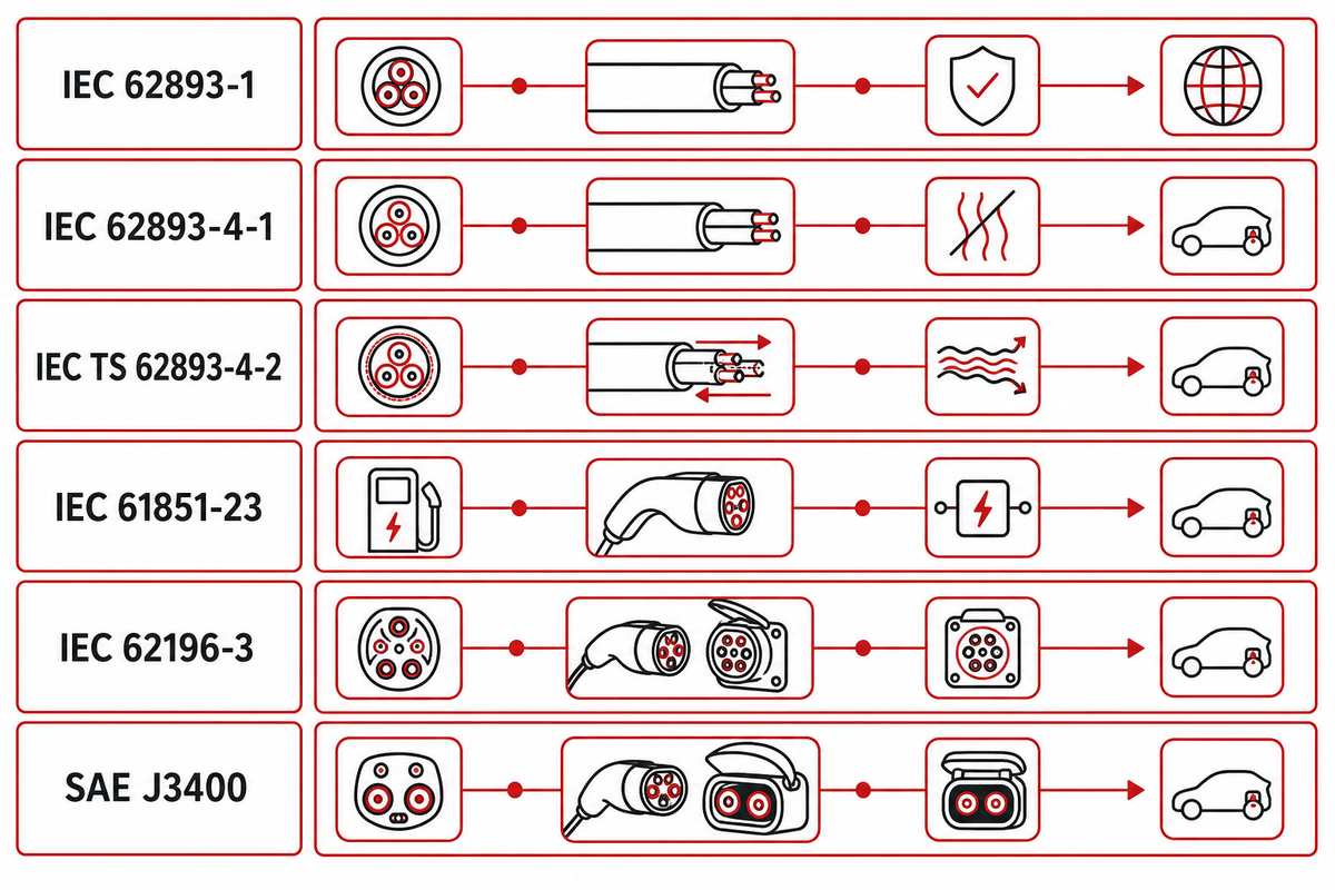
The base cable document is the starting point. Add the part that matches the architecture. IEC 62893-1 establishes general construction, dimensions and tests for flexible EV charging cables. IEC 62893-4-1 addresses Mode 4 DC cable without thermal management; IEC TS 62893-4-2 addresses cable intended for a thermal-management system. The public titles and scopes support that distinction, but they do not establish that a particular assembly passed.
Next, separate adjacent objects. IEC 61851-23 is system context for DC EVSE. IEC 62196-3 concerns DC connector and inlet configurations. In the United States, UL’s EV charging-cable testing service identifies UL 2263 among relevant cable standards. SAE J3400 supplies North American conductive-coupler context. Always confirm the current edition and applicable national adoption with the certification body responsible for the project.
Standards-to-Object Map
Document or family
Governed object
Decision it can support
Claim it does not prove by itself
IEC 62893-1
Flexible EV charging cable
General construction and test framework
Complete EVSE approval
IEC 62893-4-1
Mode 4 DC cable without thermal management
Uncooled cable-scope selection
Universal current capability
IEC TS 62893-4-2
Mode 4 cable intended for thermal management
Thermally managed cable-scope selection
Pump, controller or whole-station approval
IEC 61851-23
DC EVSE
System-level charging-equipment context
Exact cable construction
IEC 62196-3
DC coupler and inlet configurations
Interface configuration context
Heat-chain performance
UL 2263
EV cable in its stated U.S. scope
Cable evaluation route
Every regional installation approval
SAE J3400
North American conductive coupler
Interface and functional context
Offered assembly certification
Adapter evaluation
Transition device
Adapter-specific safety evidence
Approval inferred from plug fit
Project validation plan
Exact cable-to-control configuration
Duty-specific release evidence
Transfer to an untested revision
For each row, record edition, publication status, jurisdiction and the exact report or certificate being relied on. “Designed to” and “tested to” are not interchangeable with “certified by.” A current catalogue record can verify a document’s status; only the relevant certificate and scope can verify a product claim.
Evidence note: The public records for IEC 62893-4-1:2020 and IEC TS 62893-4-2:2021 both identify a maximum conductor operating temperature of 90 °C. That is a document-scope condition, not a universal surface-temperature limit or proof of assembly performance.
Build a 6-Factor Thermal Assumption Register
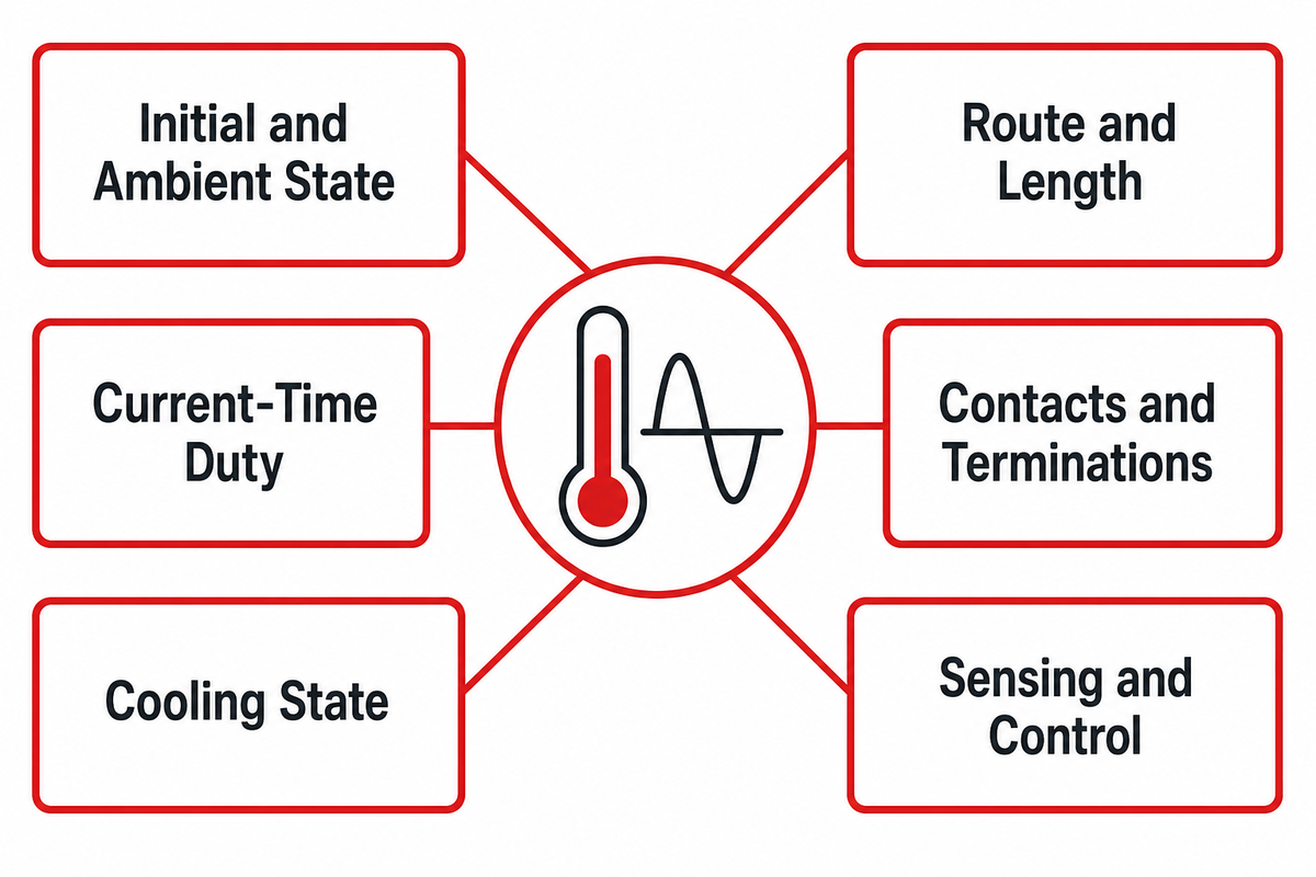
Before comparing two current claims, freeze six conditions: starting and ambient temperature, cable route and effective length, current-versus-time duty, contact and termination state, cooling state, and sensing or control logic. If any of the conditions change, the test result relates to a different question.
The register addresses a frequent error in comparing identical peak-current labels despite the fact that one assembly may start cold and run briefly while the other starts heat-soaked and carries the full load. Cable routing changes heat rejection. Contact resistance may place the hottest point at the termination. A controller may limit current before the passive device reaches the same temperature.
6-Factor Thermal Assumption Register
Factor
Value to freeze
Measurement owner
Mismatch consequence
1. Initial and ambient state
Starting temperatures, ambient range, soak method
Test laboratory
Different thermal headroom
2. Route and length
Effective length, lay, bundling and enclosure
Cable engineer
Different heat rejection and resistance
3. Current-time duty
Ramp, plateaus, steps and total duration
EVSE systems engineer
Peak label masks energy input
4. Contacts and terminations
Part revision, crimp method, condition and torque where applicable
Connector owner
Localized resistance changes
5. Cooling state
Medium, inlet temperature, flow and fault mode
Thermal-system owner
Heat-removal path changes
6. Sensing and control
Sensor locations, thresholds, derating and shutdown logic
Controls engineer
Protection response changes
Consider two hypothetical assemblies both labelled for a 500 A peak. Assembly A starts at 25 °C on a defined 5 m route, carries 500 A for 10 minutes and then derates. Assembly B starts at 40 °C after a hot soak on a 7 m route, ramps to 500 A in 90 s, holds for 20 min and derates to 250 A within 20 s. Their labels match; their thermal exposures don’t. The example is a method illustration, not a rating recommendation.
“Traceability alone does not guarantee fitness for purpose.”
NIST’s boundary matters here. Applying its fitness-for-purpose warning to this validation method, a calibrated temperature channel can make a result traceable, but it cannot repair an undefined sensor position, undocumented starting state or mismatched specimen. That second sentence is an engineering inference; NIST supplies the traceability boundary, not an EV-cable test rule.
Evidence note: A hypothetical 500 A for 10 minutes profile is reproducible only when its six boundary conditions are recorded. The NIST traceability guidance supports the measurement-chain discipline while warning that traceability alone does not establish fitness for the intended decision.
Choose Passive, Temperature-Controlled or Actively Cooled Architecture
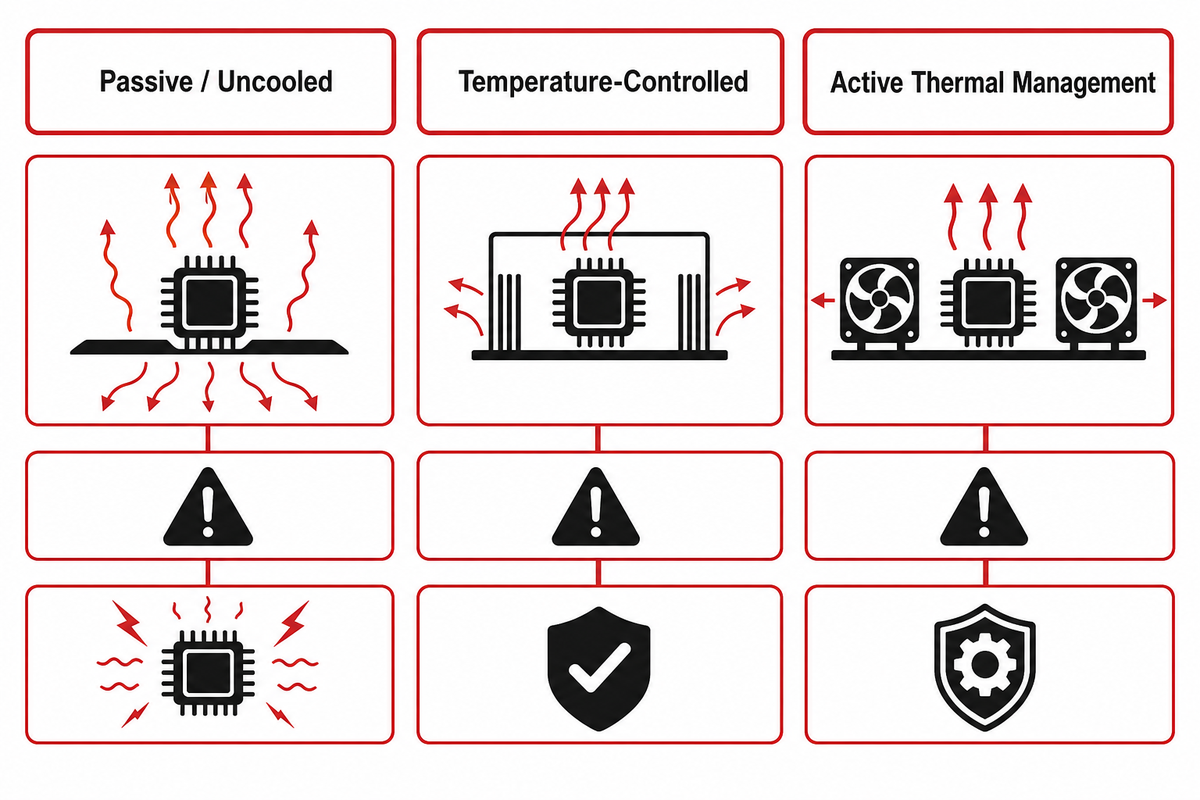
There are three evidence paths: a passive, uncooled cable, an active management system to dynamically reduce current (i.e., a temperature-controlled system), and an actively managed, cooled cable. Select among them using current-time duty, heat paths, handling constraints and credible fault response—not connector family or charger kilowatts alone. The public scopes of IEC 62893-4-1 and IEC TS 62893-4-2 separate cable without thermal management from cable intended for a thermal-management system; they do not select an architecture for a project.
Passive designs reject heat through their materials and surroundings. Their evidence must show acceptable temperature behavior throughout the declared duty and environmental range. Temperature-controlled designs add sensing and a current-control rule; the key evidence is whether sensor placement and response timing protect the actual hot points. Active thermal management adds coolant lines, fittings, flow conditions, possible leakage and a control loop, which can improve sustained performance but also creates more failure states to validate.
Three-Path Thermal-Control Architecture
Evidence question
Passive/uncooled
Temperature-controlled
Active thermal management
Primary heat-removal path
Conduction, convection and radiation
Passive path plus controlled current reduction
Coolant circuit plus external heat rejection
Added components
No cable cooling circuit
Sensors and control interface
Coolant lines, fittings, flow sensing and controls
Critical measurements
Conductor proxy, contacts and ambient
Hot points, sensor correlation and response time
Hot points, inlet/outlet temperature, flow and pressure state
Control behavior
Stay within passive validated duty
Derate or stop at defined thresholds
Maintain flow, derate on degradation, stop on unsafe faults
Failure states
Excess duty or impaired heat rejection
Sensor drift, disconnection or delayed response
Loss of flow, leak, blockage, pump or sensor fault
Recovery evidence
Return to declared initial state
Controlled recovery and event record
Fault isolation, safe current response and restart criteria
Maintenance boundary
Cable and terminations
Cable, sensors and logic revision
Full coolant path, sensors and controller
Do not turn this into a universal cooling threshold. Systems sharing the same charger power can use different voltage, current, session shape, conductor geometry, contact design and control strategies. The correct architecture is the one whose assumptions, failure cases and handling objectives can be validated together.
Evidence note: IEC separates the public scope into 3 practical paths when control strategy is included: Part 4-1 covers cable without a thermal-management system, while Part 4-2 covers cable intended for one; dynamic current reduction remains a control case that must be validated with its sensor locations and response rules.
Replay the Duty, Not Just the Peak Current
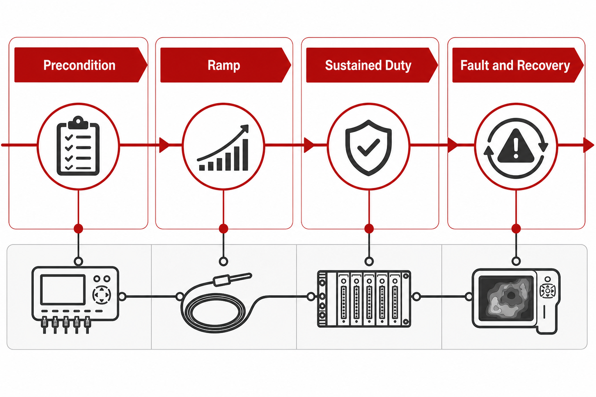
Thermal validation profiles should reproduce the sequence that creates heat: initial conditioning, current ramp, sustained or stepped duty, and derating or fault recovery. Short peaks and long plateaus may share the same maximum current while producing very different conductor, contact, housing and coolant histories. UL Solutions describes type-test reports and certification against cable standards; a project duty replay still has to define current versus time, starting state, route and cooling condition.
4-Stage DC Duty Replay
Stage
Stimulus to define
Observation to retain
Control evidence
Illustrative log syntax—not limits
1. Precondition
Ambient, soak, cable route and initial cooling state
All starting temperatures and specimen identity
Ready state and sensor plausibility
25 °C; 30 min soak; 5 m laid route
2. Ramp
Current rise rate and intermediate steps
Temperature slopes and voltage drop
Limit checks and event timestamps
0 A to 500 A in 60 s; 25 °C ambient
3. Sustained duty
Plateaus, steps, pauses and total elapsed time
Cable, contacts, housing and coolant response
Derating command and achieved current
500 A for 10 min; 40 °C ambient; 5 m route
4. Fault and recovery
Cooling, sensor or control fault appropriate to the architecture
Peak temperatures, residual state and inspection result
Detection, safe response and restart rule
500 A to 200 A in 10 s after 5 min
Record current and elapsed time at every stage, along with ambient, cable and contact temperatures. For a cooled assembly, add coolant inlet and outlet temperatures, flow state and any pressure or leak indicators relevant to the design. Record both the controller’s requested current and the delivered current; otherwise, a successful derating command can be confused with successful thermal control.
The relationship between current and the resistance of the cable (I²R) can help explain why controlling current is important, but it doesn’t help to size cables. Resistance depends on the material, length, temperature, contacts, and terminations. Rejecting heat depends on the route and construction of the cable and the cooling medium. For these reasons, an “amps to cable size” calculator would be misleading.
Fault injection should be according to the system architecture. For an uncooled assembly, a case showing evidence of abnormal sustained duty should be incorporated. A thermal control system should be validated to show evidence of sensor open/short, drift, or delay. For a liquid-cooled system, loss-of-flow/degraded-flow and safe recovery should be included. Don’t incorporate a single fault if it doesn’t match the actual system architecture.
Engineering note: With resistance held constant, increasing current by 2× produces 4× the resistive heating rate. Real cable systems do not hold resistance or heat rejection constant, so this relationship explains sensitivity; it does not replace the four-stage, configuration-specific validation profile.
Validate the Whole Cable-to-Contact Heat Chain
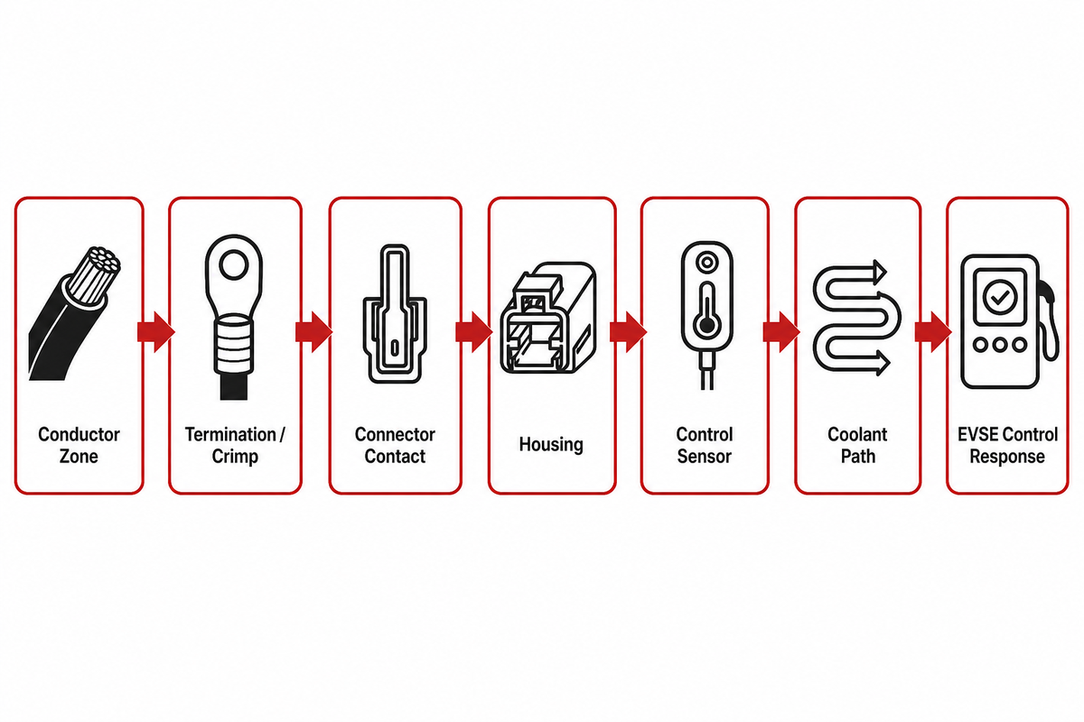
Include evidence from all points along the heat chain: conductor, termination or crimp, connector contact, housing, sensor position, coolant inlet and outlet (when present) and the EVSE control response. A cool cable body doesn’t prove that a contact or termination is controlled under the same duty. The UL Solutions charging-cable testing page treats cable testing and certification as assembly-evidence tasks; it does not turn a connector result or one temperature reading into whole-assembly approval.
Start with a measurement map before instrumenting the specimen. For each node, identify the location, method, channel ID, uncertainty, identity of the specimen, and who made the decision. Then indicate which acceptance rule uses the channel. System-protection sensors and laboratory thermocouples intended for validation may occupy different locations and answer different questions.
Cable-to-Contact Heat-Chain Measurement Map
Node
Measurement
Identity to freeze
Decision owner
Failure response
Conductor zone
Qualified temperature proxy and current
Cable build, length and route
Cable engineer
Reassess duty or construction
Termination/crimp
Temperature and voltage-drop trend
Tooling, process and lot
Manufacturing engineer
Process containment and retest
Connector contact
Contact-region temperature or validated proxy
Contact revision and condition
Connector owner
Derate, redesign or reject
Housing
Defined accessible and internal points
Material and geometry revision
Product safety owner
Review exposure and insulation margins
Control sensor
Reading, location and correlation
Sensor part and mounting
Controls engineer
Plausibility fault or safe shutdown
Coolant path
Inlet/outlet temperatures and flow state
Fluid, line, fitting and pump state
Thermal owner
Derate, isolate or stop
EVSE response
Commands, delivered current and timestamps
Firmware and calibration revision
System owner
Fault record and controlled recovery
The Same-Configuration Evidence Rule: don’t combine results obtained from different configurations of a cable-body, contact data from a different connector revision, coolant data from a different flow setting, or derating behavior from a different firmware build. If a substitute is made, justify the decision and determine whether bridging tests are required.
Method note: This map uses 7 measurement nodes, but the number is not a prescribed standard minimum. Its purpose is to force one-to-one links among physical hot points, exact specimen revisions, controller behavior and decision owners so that favorable data from different configurations cannot be assembled into a fictional result.
Keep Flex and Environment in the Same Test Story
Mechanical and environmental conditioning must stay linked to the specimen’s later electrical and thermal results. Flexing, torsion, bend transitions, abrasion, low temperature, water exposure, coolant compatibility and termination strain can interact. Separate certificates are insufficient when the final performance result cannot be tied to the conditioned assembly. The UL Solutions charging-cable testing page identifies standards-based cable evaluation, while specimen identity and conditioning sequence remain part of the project validation record.
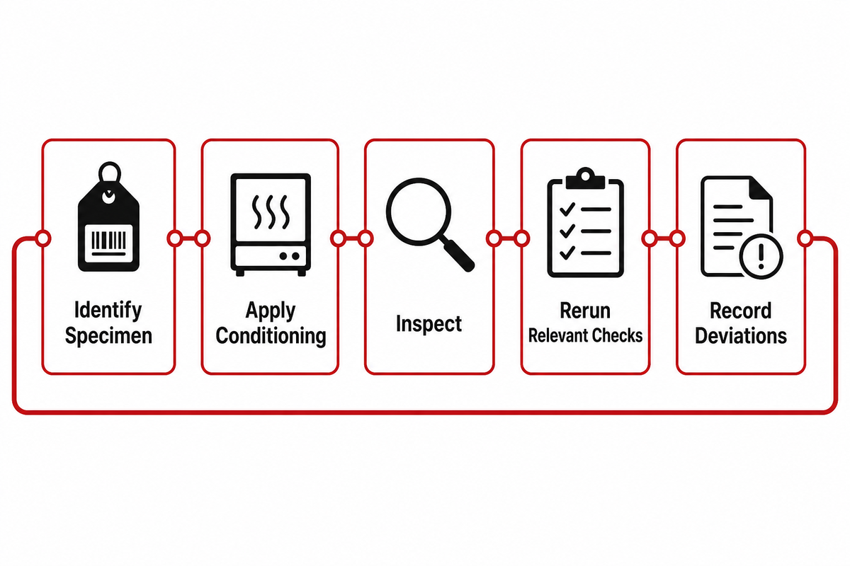
Use a five-step sequence: identify the exact specimen, apply the defined conditioning, inspect it, rerun the relevant electrical or thermal checks, and record deviations with disposition. The post-conditioning check should target the plausible damage path. For example, flex history may justify renewed conductor continuity, voltage-drop, insulation and thermal checks rather than a visual inspection alone.
Preserve conditioning history on the same record as the duty replay. Include fixture, bend location, temperature state, exposure medium, number of completed cycles where applicable and interruptions. A configuration change, e.g. a termination replacement, fitting rework or sensor movement, must be shown in the record together with the earlier results that are no longer transferable.
Do not make this section a routine field inspection. In-service inspection and stop-use decisions belong to the operating organization’s maintenance program. Here, the narrower question is whether design-validation conditioning and the subsequent result belong to the same specimen and revision.
Method note: The 5-step specimen trail—identify, condition, inspect, retest and disposition—keeps mechanical history attached to the engineering decision. It does not replace any cycle count or acceptance criterion in the applicable standard; those values must come from the selected test program and jurisdiction.
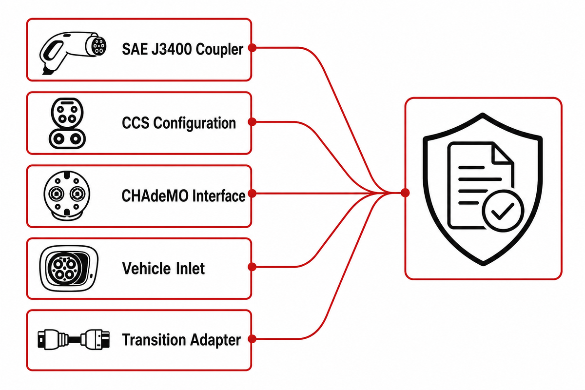
Map J3400, CCS and CHAdeMO Coupler Requirements Without Treating Them as Complete Cable Approval
The standards for couplers outline interfaces, and don’t provide blanket approval for cables, thermal-management loops, or complete chargers. J3400, CCS and CHAdeMO choices influence contact layout, communication context, packaging and regional deployment. Each cable-to-control configuration still needs its own construction, heat-chain and fault evidence.
This distinction matters during North American interface transitions. The Joint Office describes SAE J3400 publication and adoption context, while SAE defines J3400’s coupler-level scope. Those records can support an interface decision. However, those records do not validate a safety case for a conductor of a given size, termination, coolant system or derating.
Interface and Adapter Implication Table
Object
Official context
Cable consequence to investigate
Separate evidence required
SAE J3400 coupler
North American conductive interface
Contact package, sensing, termination and control integration
Exact cable assembly and EVSE evaluation
CCS configuration
Combined charging interface family
Connector geometry, contact heat path and communication integration
Regional cable and system evidence
CHAdeMO interface
Defined DC charging interface
Matching coupler, communication and assembly design
Applicable cable and charger validation
Vehicle inlet
Vehicle-side mating object
Contact pairing, locking and temperature interaction
Vehicle-side approval and compatibility
Transition adapter
Separate device between unlike interfaces
Added contacts, resistance, mass and thermal bottlenecks
Adapter temperature, endurance and fault evidence
Site deployment
Installed charging environment
Ambient, reach, routing and operating duty
Commissioning and local compliance
Offered cable revision
Project-specific assembly
Construction, termination, sensors and cooling state
Configuration-matched validation packet
Control revision
Firmware and calibration state
Derating, shutdown and recovery behavior
Version-controlled functional evidence
Certification mark
Scoped third-party claim
Confirm model, standard, edition and limitations
No transfer beyond the certificate scope
The Joint Office calls out physical compatibility with safety and certification when discussing the use of transition adapters, indicating that transition adapters require independent validation. A defensible file should include analysis and/or test data demonstrating temperature behavior, endurance, vibration, and exposure to drive-over conditions (where applicable), insulation resistance, short-circuit behavior, and continuity of grounding. A plug fit alone doesn’t address these.
Freshness note: The Joint Office records J3400 publication in December 2023 and manufacturer transition commitments beginning in 2025. The dates describe adoption context, not a technical approval. Confirm current vehicle, adapter, station and standards status for each deployment.
Assemble a Cable-to-Control Validation Passport
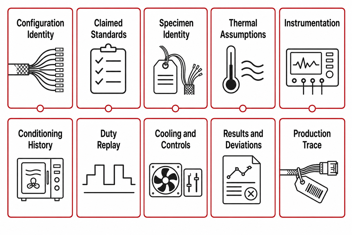
The validation passport should be traceable to the exact specimen and include assumptions, conditioning, instrumentation, duty, temperature and cooling state, controller revision, results and the release decision. It shouldn’t be separated from the configuration that produced the charts, and shouldn’t serve as a surrogate for system certification.
Cable-to-Control Validation Passport
Passport field
Minimum content
Release question
Configuration identity
Cable build, length, terminations, coupler and revision
Is this the offered configuration?
Claimed standards
Document, edition, object, jurisdiction and evidence type
Is each claim within scope?
Specimen identity
IDs, lot, process records and rework history
Can every result be traced?
Thermal assumptions
All six registered factors
Does the test match the intended duty?
Instrumentation
Locations, channels, calibration and uncertainty
Were the relevant hot points measured?
Conditioning history
Mechanical and environmental sequence
Did the tested specimen receive the stated exposure?
Duty replay
Four stages, current, time and temperatures
Was the complete thermal history reproduced?
Cooling and controls
Flow state, sensors, thresholds, firmware and events
Did protective behavior match the declared revision?
Results and deviations
Acceptance owner, anomalies, disposition and retest
Is the release decision explicit?
Production trace
Controlled drawings, process checks and change triggers
How is validated intent preserved?
The passport should state what it does not cover. Adapter certification, complete-EVSE evaluation, vehicle-inlet evidence and site commissioning remain separate. Even a traceable measurement can be irrelevant if it came from another cable length, sensor location or control revision. That is why configuration identity appears before the charts.
Once your team has a frozen duty profile and interface decision, the EV DC charging cable solutions page is the appropriate commercial handoff for configuration review; the EV charging cables hub keeps the broader product family separate. For company identity and operating background, start at Jinyou Cable and review the company background. Neither link is used here as independent technical proof.
Conclusion: Turn Your Duty Profile Into a Reviewable Validation Brief
Prepare the intended interface, current-versus-time duty, ambient range, cable route, cooling state and required standards. Jinyou’s engineering team can review the configuration boundary and identify the evidence still needed.
A DC charging cable is a flexible high-power connection used between a DC EVSE and a vehicle interface. Depending on the design, it can include power and protective conductors, signal elements, contacts, terminations, temperature sensors and coolant lines. Validation must identify the exact cable build, both terminations, coupler, sensors, cooling state and controller revision. The inlet, adapter and complete charger remain separately governed objects, so evidence for one does not approve the others.
Does a higher-kW charger always need a liquid-cooled cable?
No. Nameplate power alone does not choose the architecture. Voltage, current-versus-time duty, conductor and contact design, ambient, cable route, handling target, sensor locations and current-control strategy all matter. A passive, temperature-controlled or actively cooled design is defensible only when its declared duty and failure behavior are validated as one configuration.
What is the difference between IEC 62893-4-1 and IEC 62893-4-2?
IEC 62893-4-1 covers Mode 4 DC charging cable without thermal management, while IEC TS 62893-4-2 covers cable intended for a thermal-management system. That distinction helps to select the appropriate cable document. It doesn’t mean that an assembly, pump, controller, or complete charging station has been certified.
Can voltage rating determine a DC charging cable’s current capacity?
No. Voltage rating addresses insulation and electrical-withstand questions, while current capability is primarily a thermal-system question involving resistance, duty, contacts, route, ambient, cooling and controls. Both are necessary inputs, but neither can be converted into the other with a universal rule.
Does SAE J3400 or NACS change cable validation requirements?
SAE J3400 or NACS changes the interface context and can affect contacts, packaging, sensing and regional compatibility. It doesn’t reduce the need to assess cable construction, terminations, heat flows, thermal management, current control and faults. Adapters add another independently assessed item during a transition as opposed to transferring approval automatically. Validation records should identify the interface revision, contact design, temperature-sensor arrangement and any adapter in the tested configuration instead of treating the connector name as cable approval.
What records belong in a thermal validation packet?
Include configuration and specimen IDs, standards and scope, six thermal assumptions, instrumentation and sensor locations, conditioning history, the four-stage duty profile, coolant conditions where used, controller and firmware revision, raw and processed results, deviations, acceptance ownership and change-control triggers. Every chart should resolve back to the same declared configuration.
Shanghai Jinyou Jinhong Intelligent Electric Co., Ltd. has focused on new energy cable manufacturing since 2006, supporting solar/PV, energy storage, EV charging, and industrial or special-cable applications.
Use this guidance to prepare a clearer engineering or procurement discussion: operating environment, conductor and insulation expectations, route length, voltage, installation method, and project schedule.
Certificate evidence should be matched to the construction being specified. Public certificate evidence applies to H1Z2Z2-K solar cable constructions and should not be read as blanket certification for every JINYOU Cable product family.
PROJECT BRIEF
Move from article to specification
Share the application, required cable family, target standard, quantity range, and delivery window. The team can help structure the next engineering and procurement conversation.