Get in touch with JINYOU Cable Company

-
CALL US +86 181 1623 2461
-
EMAIL sales@jinyougroup.cn
Offshore Photovoltaic Cable for Floating and Coastal PV Arrays
- We return enquiry responses within 24 hours on business days
- Small-batch orders ship in up to 30 days after specification approval
- Listed nominal conductor areas from 1.5–240 mm²
- Custom OEM cable design for unique installation environments
Jinyou Cable supplies a water-resistant photovoltaic cable route for floating, coastal and other exposed photovoltaic direct-current arrays. Review separates fixed array leads, moving transitions, fixed submerged sections and collection or export circuits before recommending a construction. It starts with your water exposure, ultraviolet radiation, temperature, movement, bend duty, connector position and target standard, so an offshore label never substitutes for a usable specification.
Request a Specification Review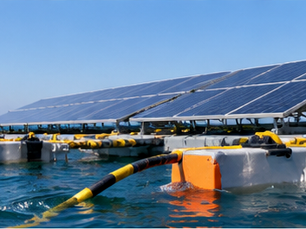
Send Your Exposure Profile
Send the installation location, freshwater or saltwater exposure, splash or immersion condition, direct-current voltage, conductor area, cable length, routing support, connector arrangement and required test documents. Those inputs become the written engineering review.
Listed conductor range
1.5–240 mm² nominal conductor area
Enquiry response
Within 24 hours on business days
Small-batch schedule
Up to 30 days after specification approval
Production schedule
Up to 6 weeks after specification approval
Evaluation samples
Standard samples may be supplied; freight and custom-sample cost are confirmed before dispatch
OEM scope
Custom OEM cable design for unique installation environments
Exposure-Driven Cable Configuration
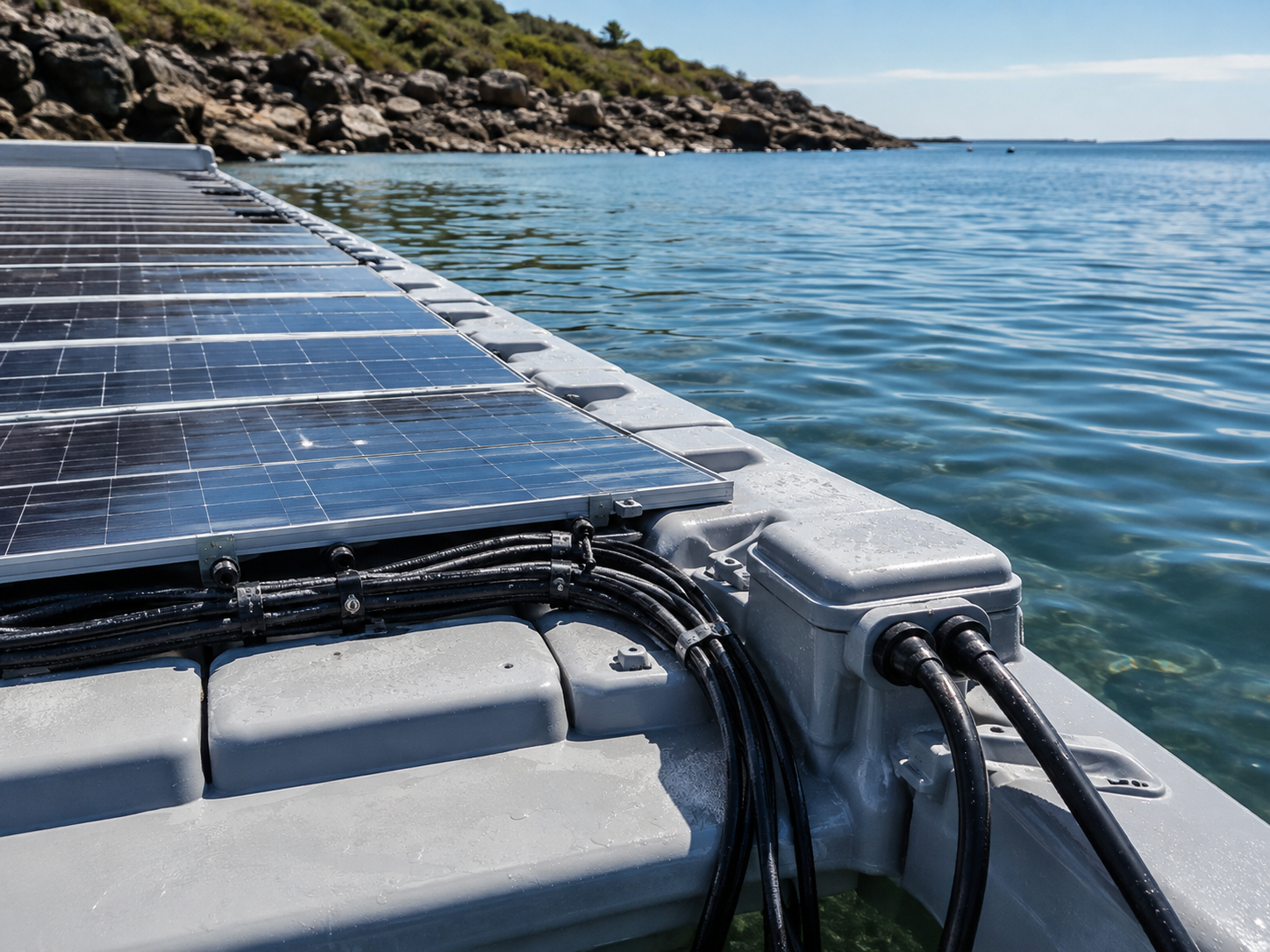
Offshore photovoltaic cable selection is a route-and-exposure decision, not a single waterproof rating. Floating photovoltaic (FPV) projects place solar panels on reservoirs and other water surfaces; offshore solar installations add salt spray, movement and connector exposure. This solar power route still needs a photovoltaic cable construction matched to the electrical and mechanical duty. The solar cable path is then checked against the route, not labeled safe by a generic waterproof term. Electrical review maps duty and physical environment to a construction, then records the tests, drawings and connector details that must be confirmed before production. This approach keeps a floating array cable distinct from a subsea transmission system.
Application
01Fixed Array Leads
For cable kept on a floating structure or support frame, the review covers ultraviolet radiation, salt spray, temperature cycling, bend radius, abrasion points, restraint and connector elevation. Current, voltage drop, protection and the owner’s wiring schedule are aligned with the listed conductor area.
Application
02Moving Transition Sections
Where a floating row moves relative to a fixed support, we review movement frequency, slack, minimum bend, strain relief, repeated flexing and replaceable interface sections. A static photovoltaic cable construction is not automatically a dynamic cable qualification.
Application
03Fixed Submerged Sections
For an intentionally submerged section, we record water type, immersion duration, depth or hydrostatic head, temperature, mechanical protection and the test protocol. Continuous immersion remains a project-specific requirement rather than an automatic consequence of a water-resistant sheath.
Application
04Collection and Export Circuits
Collection or export circuits may require a separately engineered power-cable system, protection study, switching plan, earthing, PV control cable, insulation monitoring and earth-fault response. Those responsibilities stay separate from a photovoltaic array-cable quotation until the written scope is approved.
SPREAD 1 / 4
| Exposure or route | Inputs to provide | Construction review | Evidence to request |
|---|---|---|---|
| Humid coastal air | Ambient range, salt level, sunlight and support details | Insulation, protective outer layer, ultraviolet and corrosion exposure | Material statement, dimensions and inspection plan |
| Salt spray or splash | Water chemistry, spray frequency, drainage and connector height | Water-resistant construction, sealing interfaces and abrasion control | Declared test method and installation drawing |
| Intermittent immersion | Wet/dry cycle, depth, temperature and recovery period | Water ingress path, sheath integrity, bend duty and strain relief | Immersion protocol and sample evidence |
| Continuous immersion | Duration, depth, hydrostatic head and maintenance access | Dedicated qualification plan; do not infer from salt-spray hours | Project acceptance criteria and test report |
| Floating-platform movement | Movement frequency, slack, bend radius and restraint points | Dynamic transition design, abrasion protection and connector elevation | Routing drawing, bend calculation and inspection hold point |
IEC 62930:2017 provides a photovoltaic direct-current cable baseline up to 1.5 kV; it does not by itself prove continuous submersion, dynamic movement, marine connector sealing or project acceptance. These route classes are not interchangeable, so those questions remain visible in the quotation package.
Construction Options for Engineering Review
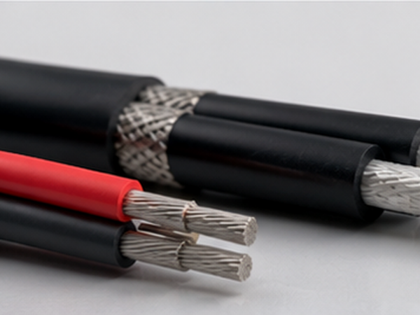
We provide custom OEM cable design for unique installation environments. Construction review begins with the conductor class and nominal area, then checks insulation, protective layers, water exposure, ultraviolet radiation, temperature, flame or halogen requirements and the installation method. The final combination is written against the approved route rather than selected from one generic environmental adjective.
-
01. SPEC
Conductor and Direct-Current Duty
Copper conductor construction, nominal area, current, voltage drop, overcurrent protection and termination details are reviewed together. The listed 1.5–240 mm² range is an availability envelope, not an ampacity table for every installation.
-
02. SPEC
Cross-Linked Insulation
Insulation selection is matched to the direct-current voltage, temperature, water exposure and target standard. Each cable schedule identifies the insulation system and the acceptance test that closes the offered construction.
-
03. SPEC
Protective Outer Layer
A protective sleeve is reviewed for ultraviolet radiation, salt spray, moisture ingress, abrasion, crushing, rodent or termite exposure and direct burial where the project design allows it. Each protection claim stays tied to a stated failure mode.
-
04. SPEC
Water-Resistant Construction
Water resistance is described as a construction requirement with a route, duration and test method. A thicker sheath does nothing for an incorrectly assembled or low-lying connector, so the mated interface and drainage detail remain in the review.
-
05. SPEC
Weather and Temperature Resistance
Ultraviolet, ambient temperature, thermal cycling and installation temperature limits are recorded before a material schedule is released. Salt-spray duration is a controlled corrosion-screening input, not a conversion into long-term service life.
-
06. SPEC
Flame and Halogen Requirements
When the tender names flame performance or low-smoke, halogen-free construction, the requirement is mapped to the offered compound, test document and destination-market rule. An unverified certificate does not belong on a product listing.
-
07. SPEC
Marking and Traceability
We can review custom colour, metre marking, polarity identification, reel or roll format and batch references as part of the quotation. Installers and inspectors receive a single reference in the approved marking schedule.
-
08. SPEC
Connector and Strain Relief
We review connector elevation, sealing, bend control, strain relief and inspection access with the cable route. Every design must identify where a transition is fixed, moving, wet or replaceable before the interface is accepted.
Protection Options for Common Failure Modes
Protection is selected against the way a cable can fail in your route. This checklist separates material, routing and interface actions, because adding a stronger outer layer cannot repair a bend radius, restraint or connector problem that was never specified.
-
Failure modeMoisture ingressDesign responseWater-resistant construction, drainage and a defined inspection pointBuyer inputWater type, wet/dry cycle, immersion duration and test method
-
Failure modeSalt-spray corrosionDesign responseMaterial compatibility, protective layer and controlled corrosion screeningBuyer inputSalt exposure, rinse practice, support material and maintenance plan
-
Failure modeUltraviolet ageingDesign responseWeather-resistant compound, shade or routing protection and replacement accessBuyer inputSolar exposure, latitude, installation orientation and service interval
-
Failure modeTemperature cyclingDesign responseInsulation and sheath temperature limits with thermal movement allowanceBuyer inputMinimum and maximum ambient, conductor load and heat sources
-
Failure modeAbrasion or crushingDesign responseSupport spacing, edge protection, bend control and replaceable wear pointsBuyer inputContact surfaces, movement, installation pull and maintenance access
-
Failure modeRodent or termite exposureDesign responseProtective layer or additional mechanical protection where the route requires itBuyer inputBurial, shoreline, tray and site-pest conditions
-
Failure modePlatform movementDesign responseSlack, restraint, dynamic transition design and connector elevationBuyer inputMovement frequency, amplitude, bend radius and replacement strategy
-
Failure modeDirect-current protectionDesign responseCoordinate conductor area with voltage drop, switching, earthing and monitoringBuyer inputArray voltage/current, circuit length, protection and fault response
Listed Construction Range and Specification Review
Our listed nominal conductor areas run from 1.5–240 mm², subject to project review. A four-column table keeps the clear data from the first-party product schedule; final outside diameter, electrical performance, current rating, voltage class and target standard are confirmed against the offered construction and route.
Nominal area and dimensions form the starting schedule. Next, the technical sheet confirms conductor class, insulation and protective compounds, rated voltage, voltage-drop basis, ampacity method, bend radius, water exposure, connector interface and test documents.
| Nominal area (mm²) | Maximum conductor diameter (mm) | Nominal insulation thickness (mm) | Protective sleeve thickness (mm) |
|---|---|---|---|
| 1.5 | 1.8 | 0.7 | 0.8 |
| 2.5 | 2.2 | 0.7 | 0.8 |
| 4.0 | 2.8 | 0.7 | 0.8 |
| 6.0 | 3.4 | 0.7 | 0.8 |
| 10.0 | 4.4 | 0.7 | 0.8 |
| 16.0 | 6.2 | 0.7 | 0.9 |
| 25.0 | 7.4 | 0.9 | 1.0 |
| 35.0 | 8.9 | 0.9 | 1.1 |
| 50.0 | 10.7 | 1.0 | 1.2 |
| 70.0 | 12.2 | 1.1 | 1.2 |
| 95.0 | 14.2 | 1.1 | 1.3 |
| 120.0 | 16.3 | 1.2 | 1.3 |
| 150.0 | 18.4 | 1.4 | 1.4 |
| 185.0 | 20.5 | 1.6 | 1.6 |
| 240.0 | 23.3 | 1.7 | 1.7 |
Electrical inputs
Direct-current voltage, operating current, circuit length, parallel runs, voltage-drop limit, overcurrent protection, switching and insulation monitoring.
Mechanical inputs
Fixed or moving route, minimum bend, slack, restraint, abrasion points, pulling method, support spacing, hydrostatic head and replacement access.
Documentation inputs
Target standard, test protocol, marking, reel or roll, packing, inspection record, sample requirement and destination-market file format.
Quotation Drivers and Production Schedule
Price follows conductor metal and area, insulation and protective construction, water-exposure test requirements, marking and packaging, order length, reel or roll configuration, requested documents, sample and inspection scope, Incoterm and destination. There is no useful fixed price without those inputs; we return a written quotation against the approved boundary.
Schedule starts after specification approval. Any separate testing, destination inspection, freight, customs or installation responsibility is recorded in writing so the start point is not confused with an enquiry date.
Payment is a 30% deposit and 70% balance before shipment. Shipping is EXW or FOB; other Incoterms are available on request.
-
DriverWhat it changesInput that keeps the quote usable
-
Conductor area and lengthMaterial quantity, drum or roll plan and electrical reviewNominal area, circuit length, quantity and spare allowance
-
Water and environmentCompound choice, test plan, sealing and inspection scopeWater chemistry, immersion condition, ultraviolet and temperature profile
-
Marking and packagingPrint sequence, polarity, reel size, labels and shipment handlingMarking drawing, reel or roll preference and receiving limits
-
Documents and acceptanceSample, inspection, test report and tender-file workloadTarget standard, document list, witness points and approval owner
Enquiry responses are returned within 24 hours on business days, reviewed by an engineer. A response identifies the route boundary, open technical inputs, proposed construction and the documents needed to move from enquiry to an approved specification.
-
Order stageCommitted timingWhat it covers
-
Small-batch orderSmall-batch orders ship in up to 30 days after specification approvalApproved construction, quantity, marking, packing and agreed inspection scope
-
Production runProduction runs are scheduled at up to 6 weeks after specification approvalPlanned material, production, inspection, packing and shipment release
-
Sample evaluationStandard samples may be supplied for evaluation; freight and any custom-sample cost are confirmed before dispatchReference construction and agreed evaluation notes before a production order
Quality Controls from Material Intake to Shipment
Jinyou Cable uses automated production machinery and testing systems at our Shanghai facility. Quality review follows the approved construction and acceptance criteria, from conductor and compound records through production checks, finished-cable inspection and packing verification. This gives the buyer a traceable decision record without turning a named standard into an unverified product certificate.
Order Control Steps
- Review conductor construction, nominal area, insulation and protective-layer inputs against the approved technical sheet.
- Confirm material and environmental documents, target standard, test method, marking and route-specific acceptance points.
- Run production-process checks and record dimensions, appearance, marking and the agreed electrical or mechanical inspection items.
- Release finished cable after the agreed inspection, packing and shipment-document review; record any open action against the same written criteria.
Engineering Review Record
The record captures the approved exposure profile, route boundary, conductor area, construction, connector interface, bend controls, target standard and requested documents before the production baseline is released.
Shipment File
Reel or roll identification, marking, packing condition, quantity, inspection records and shipment documents are confirmed against the quotation and approved specification.
Standards Target Review
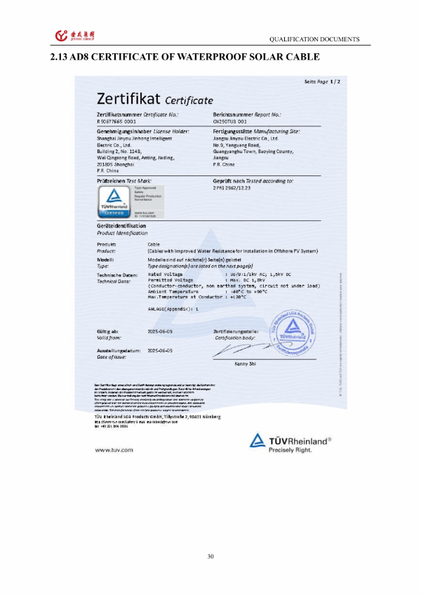
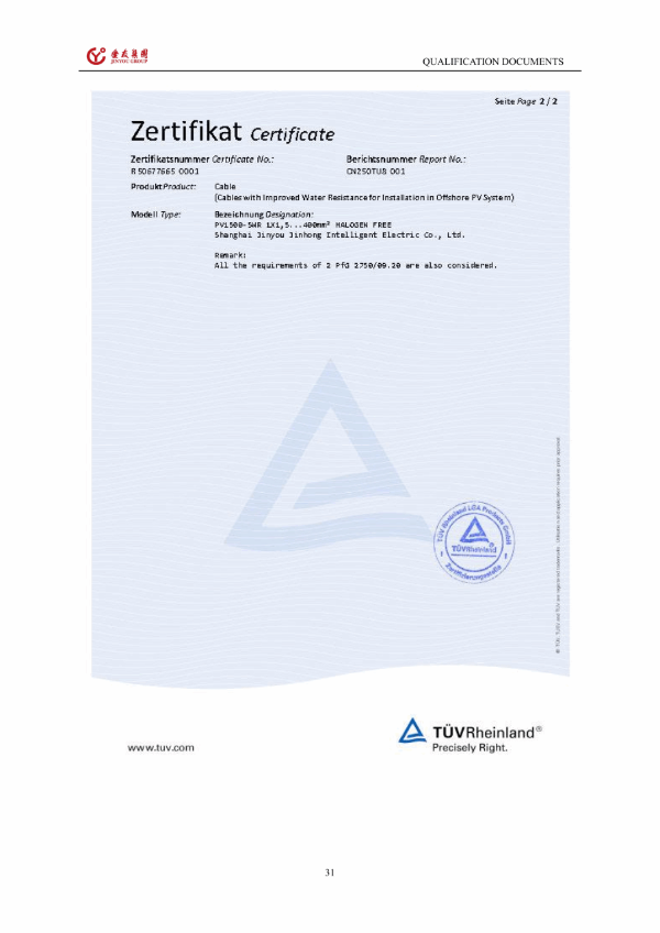
When a tender names IEC 62930, BS EN 50618 or TÜV Rheinland 2PfG 2750/09.20, the offered construction and available test documents are compared with the project target before quotation approval. DNV floating-solar guidance and DNV-RP-0584 help frame system and station-keeping questions; they do not substitute for a cable product approval.
From Exposure Profile to Shipment
A six-step review keeps engineering, procurement and project management on the same route and acceptance record.
STEP 01
Submit the exposure profile
Provide water type, splash or immersion condition, ultraviolet, temperature, movement, bend, connector and route details.
STEP 02
Confirm electrical duty
Provide direct-current voltage, operating current, conductor area, circuit length, voltage-drop basis, protection, switching and earthing inputs.
STEP 03
Freeze the scope boundary
Separate array leads, moving transitions, fixed submerged sections and collection or export circuits before a construction is offered.
STEP 04
Review construction and sample
A proposed material, dimension, marking, packing and test-document schedule is issued; standard samples may be supplied for evaluation.
STEP 05
Approve the specification
Agreed route, construction, inspection, documents, schedule and commercial terms become the production baseline.
STEP 06
Produce, inspect and ship
Process checks, finished-cable inspection, packing verification and shipment documentation follow the approved record.
Buyer Input Checklist
Route
Fixed array, moving transition, fixed submerged or collection/export circuit; support, slack, bend, abrasion, connector elevation and maintenance access.
Environment
Freshwater or saltwater, splash, intermittent or continuous immersion, depth, temperature, ultraviolet, salt-spray exposure and cleaning practice.
Commercial file
Conductor area, length, quantity, reel or roll, marking, target standard, test documents, sample, inspection, destination and Incoterm.
First-Party Product and Factory Evidence
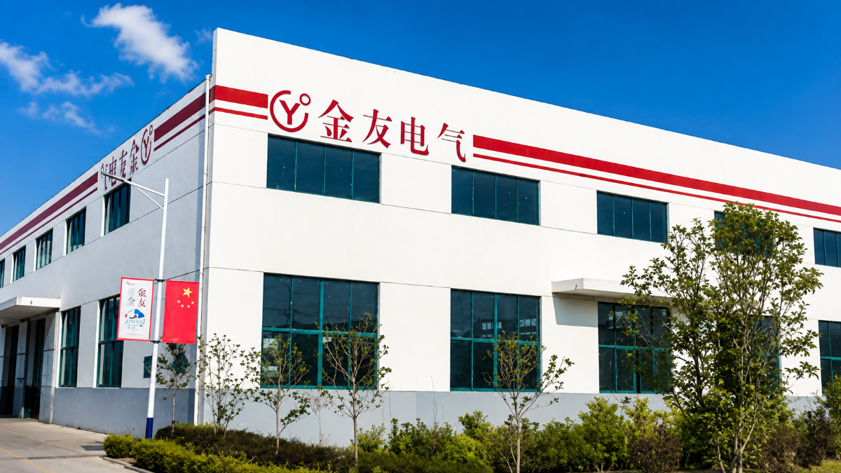
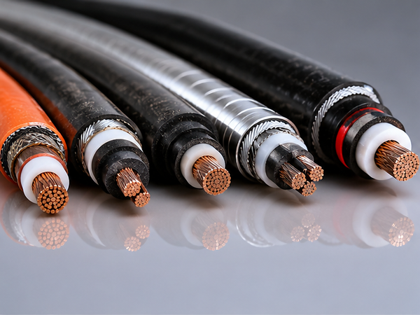
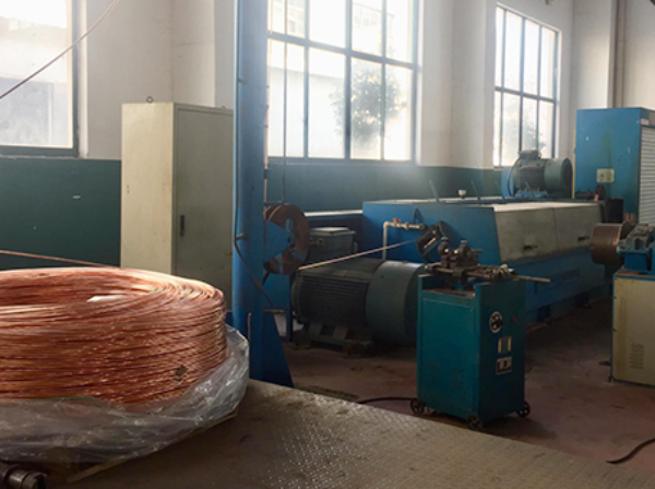
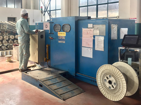
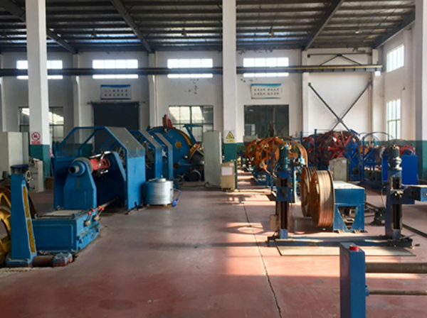
These first-party photographs come from Jinyou Cable’s existing product and factory materials. They show the cable product and manufacturing context; they are not a substitute for a route-specific test report or a named offshore project case.
PRODUCTION BASE
Company and Production Context
Jinyou Cable was established in 2006 and is based in Shanghai. Automated production machinery and testing systems support renewable-energy cable work at the Shanghai facility.
GLOBAL OEM
OEM and Export Support
We provide custom OEM cable design for unique installation environments. Jinyou Cable is a trusted supplier in over 40 countries and uses the approved specification as the reference for each order.
Selection Boundaries for Other Cable Systems
The right decision sometimes means separating a route or adding a specialist review. These boundaries are stated early so a low quotation does not hide an unclosed interface or an unsuitable duty. The wrong choice costs you in rework, replacement exposure and a delayed approval.
The matrix is a decision aid, not a lifetime prediction.
ISO 9227:2022 defines salt-spray methods and their boundaries; its test hours must not be converted into a long-term corrosion lifetime. This test is not a substitute for a service-life study. Use the result to set a controlled screening and inspection plan.
Discuss a Boundary or Alternative Route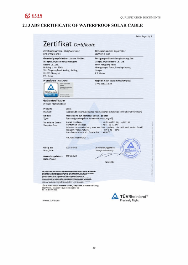
-
Situation Subsea export or transmission runWhy it is insufficient Power-cable design, joints, protection, installation and acceptance exceed an array-lead scope.What to do next Use a separately engineered subsea power-cable system and define the handover point.
-
Situation Continuous immersion is not definedWhy it is insufficient Duration, depth, water chemistry and test protocol determine the actual requirement.What to do next Freeze the exposure profile and acceptance plan before selecting the construction.
-
Situation Movement exceeds the reviewed bend dutyWhy it is insufficient Repeated flexing, strain and abrasion can concentrate at unsupported transitions.What to do next Add routing support or select a dynamic-rated construction with its own qualification.
-
Situation Connector sits in a wet or low-lying positionWhy it is insufficient Cable sheath performance cannot close a mated-connector sealing or drainage fault.What to do next Raise or redesign the interface, confirm sealing and add an inspection point.
-
Situation Target standard is unknownWhy it is insufficient A standard name without scope, edition and document owner cannot close tender acceptance.What to do next Send the owner specification and jurisdiction for a clause-by-clause review.
Offshore Photovoltaic Cable Engineering & Selection Tools
Assess offshore environmental stress factors including saltwater spray, high humidity, and extreme marine UV radiation for cable insulation selection.
Calculate voltage loss, conductor power dissipation, and cross-sectional limits across extended offshore solar array cable runs.
Validate marine project procurement specifications, offshore compliance standards, and technical parameters prior to submitting your RFQ.
Offshore Photovoltaic Cable FAQs
It is a photovoltaic direct-current cable specified for an exposed route such as a floating or coastal array. A usable specification combines conductor area, insulation, protective layer, water exposure, ultraviolet, temperature, movement, connector position, support and the target standard; an offshore label alone does not close those inputs.
No. IEC 62930:2017 gives a photovoltaic cable baseline up to 1.5 kV, while a subsea export or transmission circuit needs its own power-cable engineering, installation, jointing and acceptance boundary.
Only after the route is reviewed. A rooftop construction may address ultraviolet and temperature but still lack evidence for continuous immersion, dynamic movement, hydrostatic head, abrasion or mated-connector sealing.
Send freshwater or saltwater, splash or immersion condition, wet/dry cycle, depth, duration, temperature, drainage, maintenance access and connector elevation. Those details determine whether the route is fixed, intermittent, continuously submerged or a moving transition.
Salt spray is a controlled corrosion-screening input, while continuous immersion requires duration, depth, water chemistry and a defined test protocol. ISO 9227:2022 does not turn salt-spray hours into a long-term corrosion lifetime.
Our listed nominal conductor areas run from 1.5–240 mm². A clear product schedule includes 1.5, 2.5, 4, 6, 10, 16, 25, 35, 50, 70, 95, 120, 150, 185 and 240 mm²; current rating and voltage-drop selection require your project inputs.
Yes. We compare the offered construction and available test documents with the named project target before quotation approval. That review does not present IEC 62930, BS EN 50618 or 2PfG 2750/09.20 as a Jinyou product certificate.
Provide route type, water exposure, ultraviolet and temperature profile, movement and bend duty, direct-current voltage, operating current, conductor area, length, quantity, marking, packing, target standard, test documents, sample requirement, destination and Incoterm.
Standard samples may be supplied for evaluation; freight and any custom-sample cost are confirmed before dispatch. Send the construction, nominal area, marking and evaluation criteria you want the sample to represent.
We take a 30% deposit and 70% balance before shipment. We ship EXW or FOB; other Incoterms on request. The quotation records the destination, freight boundary, documents and inspection responsibility.
Small-batch orders ship in up to 30 days after specification approval. Production runs are scheduled at up to 6 weeks after specification approval, with the written quotation defining the order boundary and any separate test or inspection work.
Send connector elevation, mated sealing detail, strain relief, slack, minimum bend, movement frequency, support spacing, abrasion points and inspection access. A cable sheath alone cannot close a low-lying or incorrectly assembled connector interface.