Get in touch with JINYOU Cable Company

Engineering guide · Updated September 2026
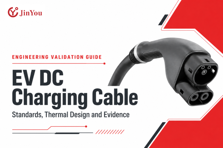
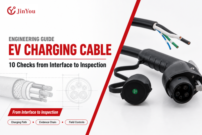
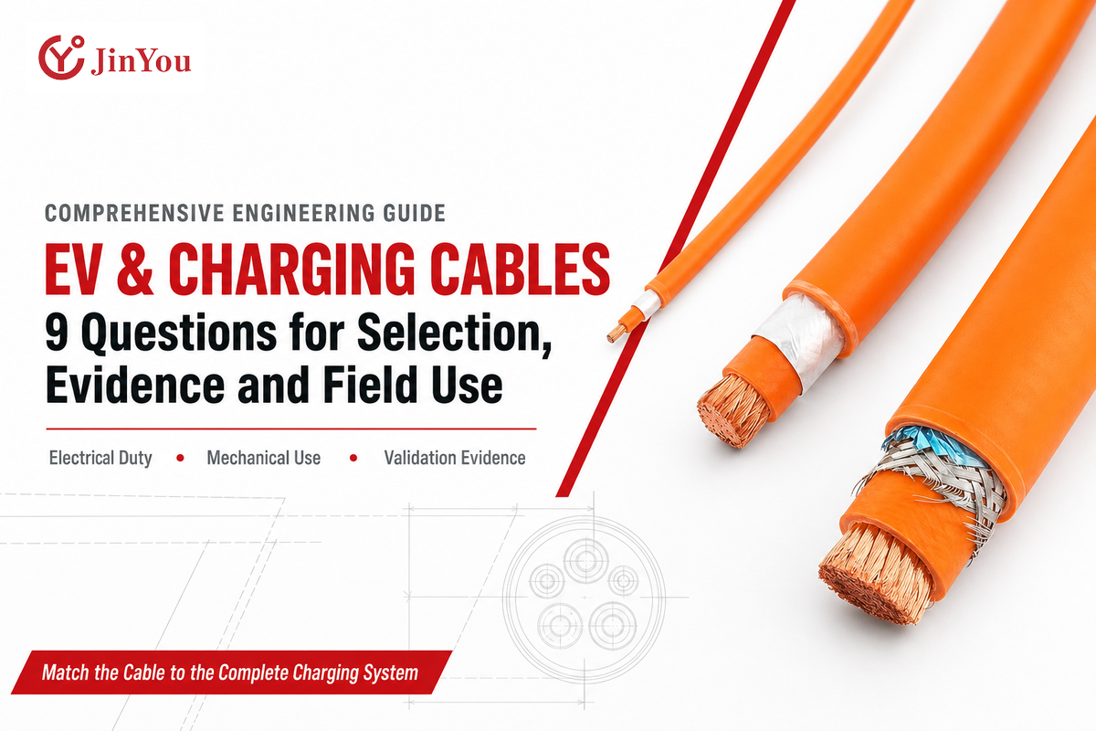
EV & Charging Cables are not suitable for a specific application just because they have the right plug; suitability also depends on duty, movement, environment, the control system, and the evidence package. This guide helps procurement, engineering, QA, operations, and maintenance teams ask better-targeted questions about cable assemblies and sets before deployment.
The short answer: choose EV & charging cables by matching six layers: interface, electrical duty, thermal behaviour, mechanical use, environment, and control or certification evidence. The connector name or ampere label answers only part of the question.
This guide is for engineering information only. Jinyou Cable’s EV and charging cable solutions page shows the company’s product offerings, catalogue configurations, and custom OEM quotation route. Product selection and quotations remain on that commercial page; this article remains informational and must not be used as installation, charging, or energized-work instructions. Appropriate regulations, approved instructions for use, the AHJ, and qualified personnel shall determine the actual engineering and electrical work scope.
Safety boundary: This article isn’t a charging procedure. Charging, repair, and energized work must follow applicable rules and approved instructions. This article is intended for informational use only. Appropriate regulations, approved equipment instructions, the AHJ, and qualified engineering or electrical personnel shall govern the actual work. Engineering and electrical services must stay within the provider’s authorized scope of practice.
1. What Exactly Are EV & Charging Cables?
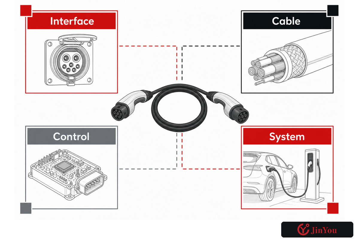
Within that safety boundary, an EV charging cable is the flexible power-transfer layer between charging equipment and the vehicle, often with signal or communication conductors and terminations. It excludes the vehicle inlet, portable control unit, connector, communications interface, and complete EVSE. Keeping these elements separate helps prevent a compatible plug from being mistaken for a validated system.
Terminology differs with each assembly. For example, a detachable Mode 3 cable may use plugs at both ends, while a tethered charger uses a non-detachable output cable. Some portable Mode 2 systems include in-cable control and protection devices. Some DC fast-charging assemblies include active liquid cooling and temperature sensing. In common usage, “cable” may name a component, while “charging assembly” and “cordset” may describe a larger construction.
The first of many questions consumers ask is usually “Type 1 or Type 2”. The Type 1 answer usually includes the J1772 AC geometry, while a Type 2 connector belongs to a different interface family. Neither description of the connector provides any description of the construction of the cable or the complete charging equipment.
Interface
Does each end physically and electrically mate?
Does each end physically and electrically mate?
Cable
Do conductors, insulation, jacket, cores, and terminations fit the duty?
Do conductors, insulation, jacket, cores, and terminations fit the duty?
Control
Are pilot, communication, sensing, and protection functions supported?
Are pilot, communication, sensing, and protection functions supported?
System
Is the complete charging equipment approved for the intended installation?
Is the complete charging equipment approved for the intended installation?
This distinction of four objects serves as the first step in an anti-error check. At the design stage, note that changing a connector family won’t resolve conductor size, insulation system, cooling, EVSE control logic, installation approval, or vehicle compatibility.
2. Which Standard Applies to Which Part of the Charging System?
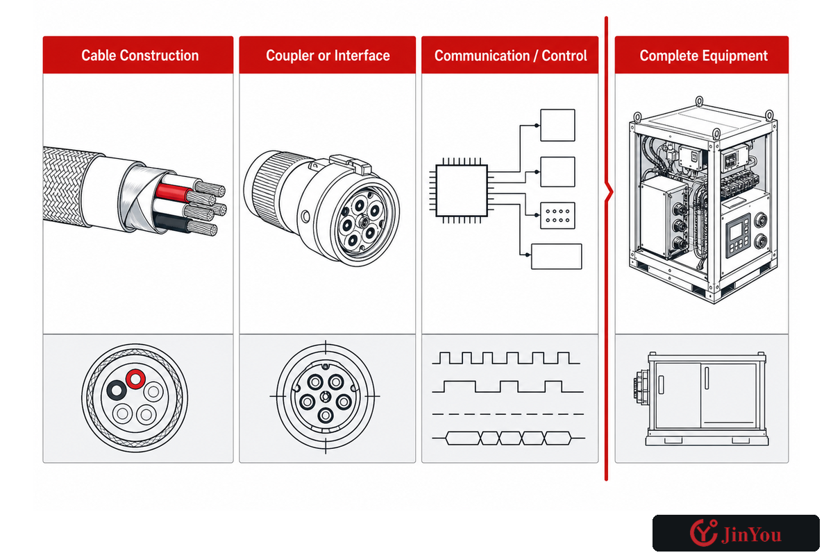
Standards should be analyzed according to object, market, edition, and claimed scope. A connector document does not automatically certify the cable, and a cable test does not approve the whole charger. The market of installation and governing standards should be identified first, with separate evidence provided for the interface, cable construction, control, and complete charging equipment.
UL Solutions’ public EV cable page illustrates the regional layer: it lists EN 50620 and the IEC 62893 series for Europe, UL 2263 for the United States, CSA C22.2 No. 332 for Canada, and JCS 4522 for Japan. This is a standards map, not a blanket permission to say that every cited document applies to one assembly.
Labels such as UL-listed, safety features, electrical safety and safe EV charging require object-level definition. Confirm what was assessed, against what edition, to ensure compatibility with the intended market and installation.
| Layer | Question | Public example | Do not infer |
|---|---|---|---|
| Cable construction | Which flexible cable requirements and tests cover this market and duty? | IEC 62893 series, EN 50620, UL 2263 | That the connector or EVSE is certified |
| Coupler or interface | What mating geometry and electrical interface are defined? | SAE J3400 for its published North American coupler scope | That the flexible cable construction fits every duty |
| Communication/control | Which signalling, sensing, protection, or charging communication is required? | Project and system documents | That a physical fit guarantees a charging session |
| Complete equipment | Is the EVSE or charging system accepted for the actual installation? | Applicable equipment rules, certification, installation documents | That a component report approves the field installation |
The official IEC Webstore entry for IEC 62893-1:2017+A1:2020 states public boundaries including rated voltages up to 0.6/1 kV AC or 1,500 V DC and a 90°C maximum conductor temperature within that part. It also limits ordinary-duty 300/500 V cable to Mode 1. These are not reasons to repeat a single number for different constructions, but rather, reasons to read the scope.
3. What Electrical Inputs Should Be Fixed Before Cable Selection?
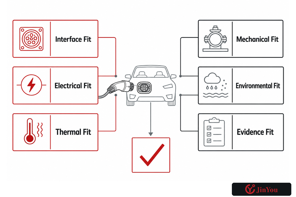
Prior to selecting a cable, fix the charging mode, AC or DC duty, system voltage, continuous and peak current, phase arrangement, expected charging profile, protective scheme, communication cores, and connector terminations as well as installation conditions. If these requirements remain poorly defined, two assemblies with the same kW rating may not be technically comparable.
Begin at the system limit. AC charging imposes limits to speed on each of the supply, charging point, cable, and the vehicle’s onboard charger. A higher rating for a Type 2 charging cable won’t result in a 7 kW charger or a vehicle capable of delivering 22 kW. In DC fast charging, the charging unit, battery acceptance, cable assembly, contact system, temperature sensing, and any cooling circuitry become a single operating chain.
Alternating current and direct current assemblies are not selected from the same assumptions; in North American AC projects, 16A, 32A, 240V, or NEMA 14-50 may appear in the brief, but the power source and kW rating don’t authorize an extension cord or replace installation review.
The table below outlines how measurable fields can be written. Every number is a synthetic notation sample, not a design value, test limit, or recommendation. Replace every sample with approved project data and the source of that data.
| Field type | Synthetic notation sample | Approved source to record |
|---|---|---|
| Nominal system voltage | 400 V | System single-line or charger data |
| Maximum DC voltage | 1,000 V | Charging-system specification |
| Continuous current | 32 A | Approved load profile |
| Peak current | 50 A | Approved charging curve |
| Charging power | 22 kW | Charger and vehicle limits |
| Charging window | 3 hours | Fleet operating plan |
| Lowest ambient | -20°C | Site climate basis |
| Highest ambient | 40°C | Site climate basis |
| Required cable reach | 5 m | Vehicle and bay route study |
| Installed bend | 100 mm | Approved construction data |
| Contact alarm example | 60°C | Validated system control basis |
| Protective response | 2 sec | Approved protection logic |
| Scheduled check example | 30 days | Site risk and maintenance basis |
| Program review example | 12 months | Owner change-control plan |
The 6-Layer Cable-to-System Fit Test
- Interface fit: vehicle inlet, EV charger outlet, plug, socket, keying, and mating arrangement.
- Electrical fit: voltage, current profile, phase, conductor arrangement, protection, and voltage-drop basis.
- Thermal fit: ambient, conductor and contact heating, duty cycle, heat rejection, sensing, and cooling state.
- Mechanical fit: static bend, repeated flex, torsion, pulling, dragging, impact, strain relief, and storage.
- Environmental fit: water, UV, oil, chemicals, abrasion, temperature extremes, contamination, and cleaning concentrations.
- Evidence fit: Edition, report scope, certified construction, production identity, and system acceptance.
An EV cable specification summary records the inputs that internal teams will freeze before comparing sample or supplier data. This gives internal teams a consistent input baseline before sample and supplier data comparison.
4. Why Is the Highest Current Rating Not Always the Best Choice?
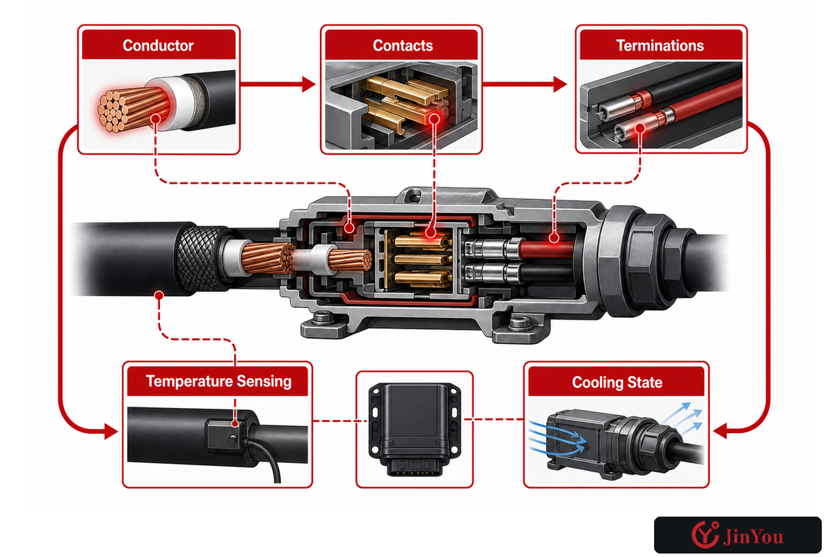
Against the input sheet above, the highest current rating alone does not make a cable the best choice. Conductor construction, contacts, terminations, routing, ambient conditions, duty cycle, heat rejection, sensing, and any cooling system all shape thermal performance. Oversizing increases cable weight and stiffness, which can make handling, storage, strain relief, and accessible use harder without reducing charging time.
Current shouldn’t be the only consideration for a purchase decision. Resistance-related heating can occur in the conductor and at various interfaces. Local problems can develop at contacts or terminations, or from lost cooling flow, inadequate strain relief, connector contamination, or inaccurate sensing. The nameplate current rating may not indicate these problems.
The public charging-cable cooling patent describes coolant paths that remove heat from conductors and connector contacts. It’s useful evidence that thermal architecture can cross the cable-connector boundary. It isn’t proof that any product reaches a claimed current, temperature, or service life.
Engineering stop: if an actively cooled cable is proposed, request the allowed current versus cooling state, sensor locations, protective response to low flow or high temperature, connector limits, alarm behaviour, and the evidence used to validate the complete assembly.
5. How Do Bending, Torsion, Dragging, and Vehicle Reach Change the Design?
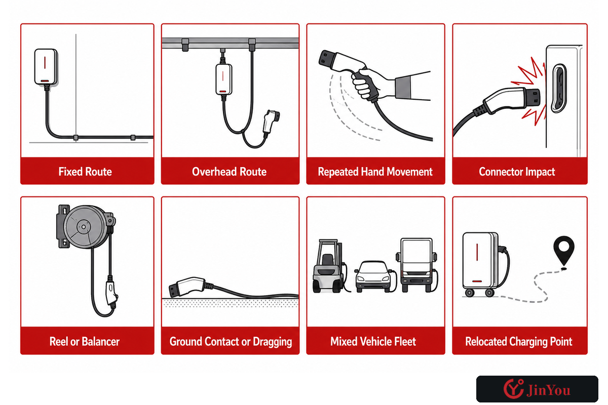
Mechanical duty cycle does not equal a single defining radius. Does the cable stay in place? Is it moved occasionally, frequently, repeatedly flexed, twisted, dragged, reeled, driven over, or supported overhead? After defining the cable’s movement, map vehicle positions, inlet locations, user reach, strain relief, connector parking, and storage so evidence matches field use.
Static bend, dynamic flex, and torsion aren’t the same. The bending cable that fits around a fixed corner may not be the best choice for multiple reeling cycles. While a longer cable may reach more electric car inlet positions, it may contact the ground, create a trip hazard, require more storage effort, and increase pulling force.
When the decision is about accessibility, some of the same factors come into play. The U.S. Access Board’s EV charging recommendations connect cable reach, varying vehicle inlet positions, maneuvering space, and accessible routes. Its 60-inch reach recommendation sits inside that accessibility context; it isn’t a universal cable-length rule for every country or site.
| Observed use | Specification question | Evidence to request | Field control |
|---|---|---|---|
| Fixed route | Minimum installed bend and support spacing? | Construction-specific installation data | Support and protect edges |
| Overhead route | What travel, retraction, tension, and connector parking occur? | Balancer and construction-specific installation data | Set travel limits and protect the route |
| Repeated hand movement | Which flex and strain-relief tests represent use? | Cycle method, specimen, result, acceptance | Inspect high-motion zones |
| Connector drop or impact | Which impact and strain-relief tests represent use? | Impact method, specimen, result, acceptance | Inspect after each impact event |
| Reel or balancer | What bend, tension, twist, and heat state occurs? | Cable-reel compatibility and thermal basis | Set travel stops and storage path |
| Ground contact or dragging | Which abrasion, cut, crush, and contamination exposures apply? | Relevant jacket and finished-assembly tests | Route away from wheels and sharp edges |
| Mixed vehicle fleet | Can users reach each inlet without blocking an accessible route? | Bay and vehicle reach study | Mark parking and connector locations |
| Relocated charging point | Can users still reach each inlet without blocking an accessible route? | Updated bay and vehicle reach study | Recheck parking and connector locations |
6. How Should Jacket and Environmental Requirements Be Specified?
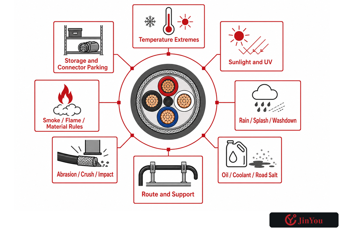
After mapping movement, do not specify the environment in general terms such as “weatherproof” or “outdoor”. Carry that movement map forward by providing the temperature, moisture, UV, and chemical exposure details. Provide the conditions and requirements for flame resistance, potential movement and storage, abrasion and cleaning, and potential contamination. The material of the jacket, fillers, insulation, seals, connectors, and markings must all be reviewed.
The use of the compound name doesn’t settle finished-cable performance. TPE, TPU, rubber, PVC, or other materials may cover many formulations and constructions. Record the exact offered construction, test method, specimen identity, result, acceptance criterion, and any conditioning used. If cold flexibility is relevant, cold-flex evidence should be provided for the specific project temperature rather than an “all-weather” claim.
- daily and extreme ambient temperature;
- sunlight and UV duration;
- rain, splash, pooling, temporary immersion, or washdown;
- oil, coolant, road salt, dust, mud, and cleaning chemicals;
- ground, reel, overhead, tray, or fixed routing;
- abrasion, crushing, cut, impact, and vehicle contact risk;
- indoor smoke, flame, or material restrictions;
- storage temperature, bend state, and connector parking.
Jinyou’s quality testing and compliance overview can assist in turning these project exposures into a test and document discussion. The final acceptance basis will remain with the buyer’s market, application, and authority.
7. What Evidence Proves That an EV Charging Cable Fits the Duty?
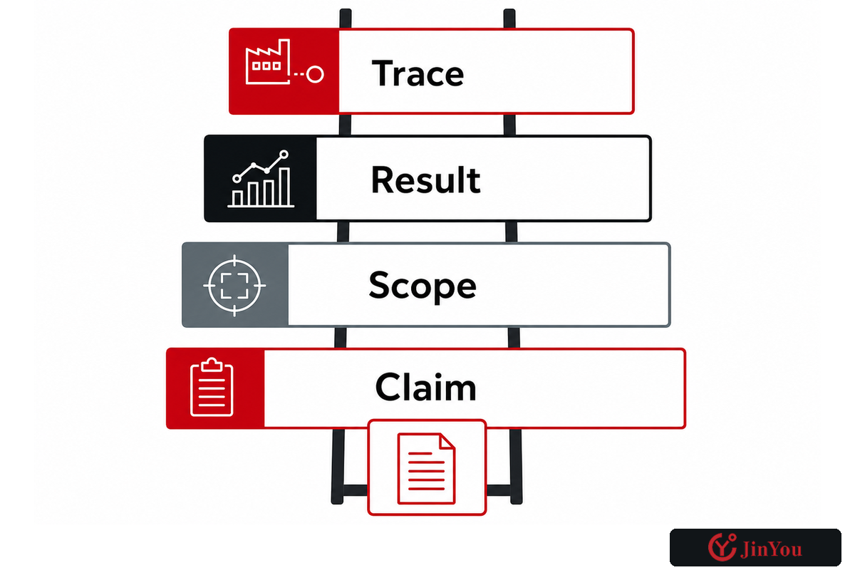
Evidence traces those project exposure requirements through to current production. Evidence that cites only the brochure or standard number is only the first rung. Stronger evidence identifies the clause and edition, tested construction, specimen and result, report or certificate scope, production identity, and controlled changes.
| Rung | Evidence | Question it answers | Remaining gap |
|---|---|---|---|
| 1 · Claim | Data sheet, drawing, standard list | What does the supplier say is offered? | No independent or test linkage yet |
| 2 · Scope | Applicable document, edition, clause, market | Does the named requirement cover this object and duty? | No proof the offered construction was tested |
| 3 · Result | Test report or certificate with specimen identity | What construction was evaluated, how, and with what result? | Production identity may still be unclear |
| 4 · Trace | BOM, drawing revision, batch or lot, inspection and change control | Is the supplied cable tied to the validated construction? | Field installation and use still need control |
To resolve discrepancies, ask for reports in a timely manner. Consider the family of cable, arrangement of conductors and cores, dimensions, materials, construction of connectors and terminators, conditioning, test method, acceptance limits, date of report, and the issuing organization. A report on a similar specimen is background evidence, not proof that a modified assembly remains validated.
Jinyou’s quality testing and traceability framework can also be used to initiate the traceability discussion. The buyer should still indicate the specific records to be retained for sample approvals, production, shipment, and notification of changes.
8. How Should Charging Cables Be Inspected and Maintained?
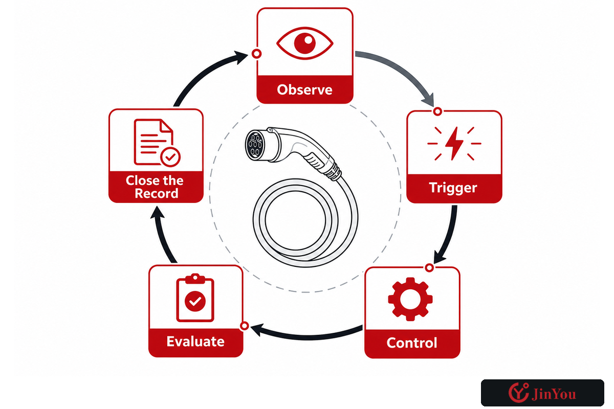
Use manufacturer instructions, applicable rules, site risk, and observed condition to set the program. Combine pre-use observation with scheduled checks and event-triggered inspection after impact, overheating, contamination, abnormal charging, repair, relocation, or heavy vehicle contact. Record the cable ID, findings, and status, as well as corrective action, test evidence, and authorization for returning the cable to service.
“Check chargers and cords for damage before using. Never use if damaged.” NFPA EV safety guidance
The U.S. Alternative Fuels Data Center recommends secure cable storage, periodic checks, and cleaning for charging infrastructure. It doesn’t publish one universal interval for every site. That absence should lead to a documented risk-based program, not to “inspect whenever someone remembers.”
Some mandatory rules are narrower and more specific. For covered portable cord-and-plug equipment and flexible cord sets in U.S. workplaces, OSHA’s 29 CFR 1910.334 text requires visual inspection before use on any shift. It provides an exception for qualifying fixed cord-and-plug-connected equipment and flexible cord sets until relocation. To determine scope, the equipment and workplace must be examined.
Inspect-by-Event Protocol
- Observe: jacket cuts, abrasion, flattening, kinks, swelling, discoloration, exposed parts, loose hardware, contaminated contacts, or damaged strain relief.
- Trigger: impact, run-over, abnormal heat, charging fault, liquid ingress, dropped connector, repair, relocation, or repeated misuse.
- Control: remove or isolate suspect equipment according to site instructions; don’t perform energized improvised repair.
- Evaluate: use qualified personnel, manufacturer criteria, and required electrical or functional tests.
- Close the record with identity, finding, disposition, evidence, approver, and return-to-service status.
9. How Should Buyers Plan for J3400 Without Stranding Existing Assets?
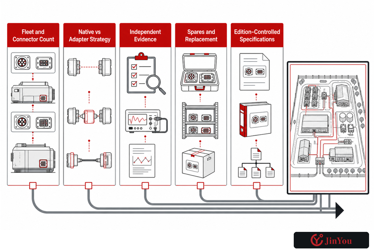
Treat J3400 as a North American interface transition rather than a universal cable replacement. Create a site and fleet plan that records vehicle inlets, charger connectors, adapter policy, AC and DC duty, certification status, replacement cycles, and legacy CCS1 or J1772 demand. Double-check installation dates because announced plans and installed assets don’t always align.
The current SAE J3400_202409 catalogue entry describes a coupler for DC and single-phase AC conductive charging. The Joint Office’s J3400 page records the path from the December 2023 Technical Information Report to the 2024 Recommended Practice stage and discusses separate certification work.
With planning, uncertainty remains. In March 2024, an FHWA request for information asked about J3400 compatibility, safety, implementation challenges, and continued market demand for CCS and J1772. The practical response is a controlled transition matrix, not a prediction that every vehicle, charger, cable, adapter, or jurisdiction will converge on the same date.
- Count actual fleets and connectors by duty and site.
- Separate native interfaces from approved adapter strategies.
- Verify cable, connector, control, and complete-equipment evidence independently.
- Plan spares and replacement assemblies for the transition window.
- Keep procurement specifications edition-controlled and date-stamped.
Frequently Asked Questions
Are all Type 2 EV charging cables the same?
No. Type 2 mainly identifies an interface family.
Even during a connector transition, cables can differ in current and voltage scope, phase arrangement, length, conductor construction, control cores, jacket compound, flex behaviour, termination quality, environmental tests, markings, and certification. Compare the complete offered assembly against the 6-Layer Cable-to-System Fit Test. Physical mating is necessary, but it isn’t evidence of electrical, thermal, mechanical, environmental, or regulatory fit.
Can a 22 kW cable be used on a 7 kW EV charger?
A properly approved 22 kW cable may operate on a 7 kW charger, but a higher cable rating does not create a higher charging rate because the supply, charger, vehicle, phase arrangement, controls, and approved instructions set the system limits.
The charging point, vehicle onboard charger, supply, phase arrangement, cable, and controls each impose limits. One suitably compatible higher-rated cable may operate at the lower system rate, but the project team must check compatibility and approval for the actual vehicle, charger, connector, and instructions. Don’t use the kW label alone to decide electrical fit or infer the delivered charging speed.
What cable length is best for an EV charging station?
The best cable length reaches every intended inlet without blocking accessible routes or creating excessive ground contact, pulling, trip exposure, weight, voltage-drop concerns, or storage effort, so it should come from a site-specific route study rather than a generic value.
Map bay geometry, vehicle approach, inlet positions, accessible routes, connector parking, and storage before choosing. Extra length can increase ground contact, pulling, trip exposure, weight, voltage-drop considerations, and storage effort. Too little length can force unsafe parking or strained connections. Use a route study and construction-specific data instead of copying a generic length from another site.
Does an IEC 62893 or UL 2263 claim prove the whole charger is certified?
No. Those references concern cable scope.
The connector, control functions, complete EVSE, installation, and local approval can require separate evidence.
Can a damaged charging cable be repaired in the field?
Do not improvise a repair.
Remove or isolate it under site rules, follow the manufacturer’s instructions, and have qualified personnel determine the required repair, tests, and return-to-service decision.
What should be included in an EV charging cable test package?
Ask for scope, specimen, method, result, and traceability.
The file should connect the applicable document and edition to the offered construction, test specimen, acceptance criterion, report or certificate, production drawing, batch or lot identity, inspection record, and controlled changes.
Turn the Guide Into a Reviewable Cable Brief
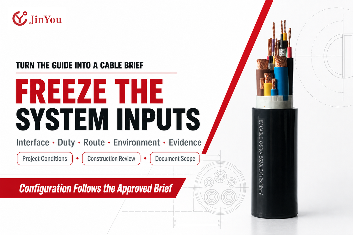
Start with the charging system instead of the product description. Freeze the six fit layers and label everything ambiguous. Require evidence at the same level of detail. If the project requires a custom build, use Jinyou’s EV cable route matrix to organize movement and exposure inputs and then engage in a technical conversation.
Need a project-specific cable review?
Provide the connector interfaces, voltage and current profile, duty cycle, cable route, movement, environment, market, and evidence. Jinyou Cable can then discuss the construction, testing, and documentation path for the actual project without treating a catalogue label as the engineering solution or replacing buyer approval.
References & Sources
- IEC Webstore, IEC 62893-1:2017+A1:2020 public scope
- UL Solutions, EV charging cable testing and certification
- Joint Office, SAE J3400 Charging Connector
- SAE International, J3400_202409 catalogue
- U.S. DOT, 2024 J3400 Request for Information
- Alternative Fuels Data Center, maintenance and operation
- U.S. Access Board, accessible EV charging recommendations
- OSHA, 29 CFR 1910.334
- NFPA, Electric Vehicle Safety tip sheet
- Google Patents, WO2015119791A1, cooling of charging cable
- Jinyou Cable, company profile