Get in touch with JINYOU Cable Company

-
CALL US +86 181 1623 2461
-
EMAIL sales@jinyougroup.cn
Industrial Line Protection
Heat Tracing Cable: Self-Regulating, Ex e II T4 Marked BL Series and Skin-Effect Constructions
We reply to your enquiry within 24 hours
Production runs are scheduled at 15–30 days
Watts per metre and maximum circuit length published for every BL model
We quote FOB China
Heat tracing cable holds process fluid above its pour point and keeps industrial lines from freezing. Jinyou Cable builds four constructions for that duty, from a cut-to-length self-regulating tape up to a skin-effect system that heats a single pipeline circuit of 200 m to 10 km. This page is written for plant, project and process engineers specifying an industrial line.
This page does not cover roof, gutter or domestic water pipes. Those circuits are sized for snow load and ice dams on a building envelope, which is a different duty class with different products and different controls.
Send a pipe schedule and a maintain temperature and our engineers will come back with a construction, a power density and a circuit plan.
Request a Quote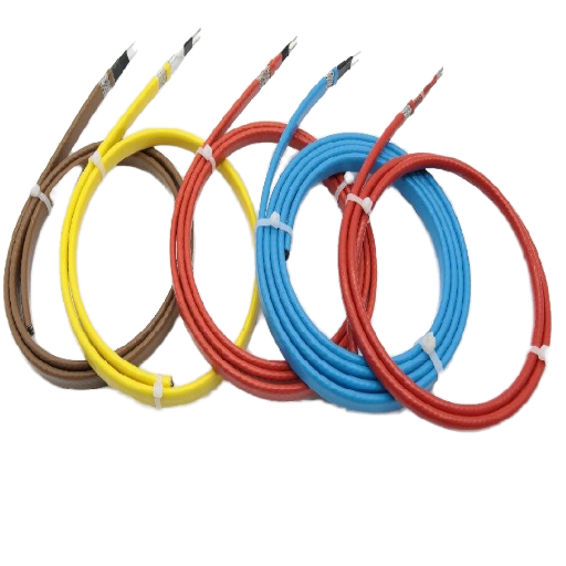
Enquiry response
We reply to your enquiry within 24 hours.
Production lead time
Production runs are scheduled at 15–30 days, counted from confirmed specification.
BL series output
10–40 W/m, published per model at 220 V.
Circuit length
100–300 m per BL model; 200 m–10 km on the skin-effect system.
Quoting terms
We quote FOB China against telegraphic transfer or letter of credit.
Engineering support
Preliminary project evaluation, cable selection advice and system integration design.
Four Heat Tracing Cable Constructions We Build
The four constructions below are not four grades of the same product. Each one is selected by a different question, and mixing their numbers is the commonest specification mistake we see on incoming enquiries.
The heat tracing cable working principle is not the same across the four. One generates heat in a conductive polymer core, one in a metal sheath, and one in the pipe’s own heat tube; for the BL series the construction is not published, so we state none.
All four are built for industrial applications: process pipework, vessels, instrument lines and long pipeline runs. An industrial heat trace specification starts from heat loss and area classification, which is why the four cards below start with what is published rather than with what sounds best.
Self-Regulating Heating Cable
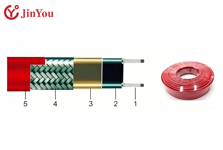
A conductive polymer is extruded between two parallel bus wires and wrapped in an insulating outer sheath. The core has a high positive temperature coefficient and works on a parallel circuit structure.
- Three colour grades: black, brown and red
- Heating is uniform without overheating across the traced length
- Cut to any length or extended within the specified scope
- Crossing and overlapping installation is permissible
- Output power adjusts to the temperature of the equipment being heated
- Maximum sustained temperature from 65 ± 5 °C to 135 ± 5 °C by grade
Not published for this construction: watts per metre, maximum circuit length, rated voltage, hazardous-area marking.
BL Series Heating Cable
A model-designated parallel heating cable rated by power per metre and by a maximum circuit length. This is the only construction for which we publish a hazardous-area marking.
- Five published models across 220 V and 380 V
- 10, 20, 30 and 40 W/m at 220 V; 20 W/m at 380 V
- Maximum circuit length 100 m to 300 m depending on model
- Rated voltage options 220 V, 380 V and 660 V
- Marking as printed on the model table: Ex e II T4
Not published for this construction: bend radius, insulation resistance, ingress protection rating.
Metal-Sheathed Constructions
Selected by sheath alloy rather than by watts per metre, for duty above the ceiling of a polymer jacket. The alloy and its recommended temperature range are the two things we publish here.
- Stainless steel 304, 316L and 321
- Alloy 825 for the corrosive high-temperature end
- Selection starts from medium and temperature, not from power density
Not published for this construction: insulation medium, power output, circuit length, rated voltage, hazardous-area marking.
Skin-Effect Heat Tracing System
A designed system rather than a tape you cut on site. Alternating current flows in opposite directions between the cable and a heat tube welded to or threaded along the pipeline, and the current concentrates on the inner surface of that tube.
- Single-circuit tracing length of 200 m to 10 km
- Power output 15 W to 270 W per metre on a single circuit
- Supply at 50 Hz AC on one of the published steps — 220 V, 380 V, 660 V, 1140 V, 6 kV or 10 kV — with a power control cabinet
- Maintain temperature up to 500 °C
- Ingress protection IP68
Suitable for pipelines, overhead pipelines, submerged pipelines and high-temperature pipelines.
Conductors, Insulation, Braid and Sheath Alloys
The commonest material failure on a traced line is a jacket asked to sit somewhere it was never rated for. A polymer grade run against a line that steams out at 200 °C does not degrade gracefully; it loses insulation resistance and the circuit trips on earth fault.
The root cause is that jacket selection gets made from the maintain temperature alone, while the number that kills the jacket is the peak the line reaches during cleaning or upset. Material selection here is therefore driven by three inputs: the temperature the cable must survive, the medium it sits in, and whether the circuit needs an earth path through a braid.
Sheath Alloys and Their Recommended Temperature Ranges
These are ranges for the sheath material, not operating envelopes for a heating circuit. The highest maintain temperature we publish for any product on this page is 500 °C, on the skin-effect system.
Where Each Alloy Earns Its Place
304
carries the widest published range of the four, −196 °C to 500 °C, and is chosen for heat resistance, oxidation resistance and mechanical strength
316L
is published from 450 °C to 650 °C and is chosen where corrosion resistance has to hold at high temperature; the molybdenum that gives it that resistance is also why it is the usual answer to chlorides
321
is published from 500 °C to 800 °C, the stabilised grade that keeps its properties further up the range
Alloy 825
is published from 600 °C to 850 °C and is chosen where the medium is both hot and aggressive
These are the alloy’s own characteristics and its recommended sheath range. Which alloy your line needs also depends on the medium and the peak, and that pairing is not something a table settles on its own
Polymer Constructions Architecture
- Heating core: conductive polymer with high positive temperature coefficient resistivity
- Bus wires: two parallel conductors with the core extruded between them
- Circuit structure: parallel, which is the reason the cable can be cut to length in the field
- Outer sheath: insulating jacket over the heating core
- Braid: specified where the installation needs an earth-continuity path and mechanical protection over the jacket
What this list does not settle:
the bus-wire conductor grade is not published for these constructions. If your specification calls out a wire standard such as ASTM B33 for tin-coated soft copper, send it with the enquiry so it can be checked against the build rather than assumed
The trade-off between a polymer construction and a metal-sheathed one is not cost alone. A polymer jacket stops at 150 °C surface temperature on our highest grade, so a line running above that has to move to a sheath alloy whatever the budget says.
We build both, which is the reason we will tell you when the cheaper polymer construction is the wrong call for your medium rather than quoting it because you asked for it.
Working out which sheath alloy your medium and peak temperature point to?
Open the sheath alloy selector →Ingress Protection and Circuit Termination
A circuit that stops holding temperature is not always a cable fault. Most heat tracing circuits fail at the ends, at the splices and under the insulation, which is where the installed cost and the warranty argument usually end up.
Published Ingress Rating
- Skin-effect heat tracing system: IP68
- Self-regulating and BL series constructions: no ingress rating is published, so the enclosure and gland selection carries that duty on those circuits
- What the rating means: IP68 is defined in IEC 60529, published in Europe as EN 60529, as dust-tight and protected against continuous immersion under conditions the manufacturer states — so the stated immersion conditions carry more information than the two digits, and a second digit of 8 does not by itself promise the jet resistance of a 5 or a 6
Termination Points That Decide Circuit Life
Knowing how to terminate heat trace cable is worth more on a site than another five watts per metre. The termination at the far end is a recognised source of ground faults to a metal pipe, because that is where moisture reaches the bus wires if the end seal is not made correctly.
Two other failure paths come up repeatedly in maintenance discussion among electricians. Continuous energization during wet weather breaks down a jacket over seasons rather than hours, and after a valve is replaced the tracing is often not reapplied correctly with the insulation left short of its original design.
Plan the following before the cable arrives.
End seal
factory-supplied kit, made up dry, before the thermal insulation goes on
Power connection & splices
in an enclosure rated for the area classification, not taped in the lagging
Earth path
braid bonded at the supply end so ground-fault protection can see a leakage current
Thermal insulation
reinstated to the original design after any valve or pump is replaced — a traced line with the lagging left off is a line without heat tracing
Ground-fault protection
required for pipeline and vessel heating equipment under NFPA 70 Article 427.22, and treated as a continuous load for circuit sizing
Temperature Classes, Power Output and Circuit Length
A heat tracing cable specification that stops at watts per metre is only half written. Two numbers decide the rest: how hot the line has to stay, and how long the circuit is.
Every BL model is published with a rated output in watts per metre. The output your line needs is a different number, and it comes from the insulated heat loss rather than from the cable. Calculation rules for that heat loss are published in standards such as ISO 12241, which is where the maintain temperature, the lagging and the minimum ambient turn into a power density.
The Three-Temperature Screen
A heating cable does not have one maximum temperature. It has three, and they are checked in order, because a cable that clears the maintain temperature can still fail the withstand temperature during a steam-out.
| Construction and grade | Maximum maintain | Maximum exposure | Maximum withstand |
|---|---|---|---|
| Self-regulating, black | 65 ± 5 °C | 85 ± 5 °C | 90 °C |
| Self-regulating, brown | 105 ± 5 °C | 125 °C | 130 ± 5 °C |
| Self-regulating, red | 135 ± 5 °C | 150 °C surface | not published |
| BL series, J3 sheath code | see model table below | not published | 205 °C |
| BL series, J4 sheath code | no model row published | not published | 260 °C |
| Skin-effect system | up to 500 °C | not published | not published |
Note: Read each row on its own line. A rung from one row does not carry across to another row, because the constructions differ in both jacket material and circuit design.
BL Series Model Table
| Model | Rated voltage | Rated power | Max circuit length | Max maintain temp | Max withstand temp | Marking printed |
|---|---|---|---|---|---|---|
| BL-10-V2-Q-J3 | 220 V | 10 W/m (3.0 W/ft) | 200 m | 150 °C | 205 °C | Ex e II T4 |
| BL-20-V2-Q-J3 | 220 V | 20 W/m (6.1 W/ft) | 120 m | 140 °C | 205 °C | Ex e II T4 |
| BL-30-V2-Q-J3 | 220 V | 30 W/m (9.1 W/ft) | 100 m | 125 °C | 205 °C | Ex e II T4 |
| BL-40-V2-Q-J3 | 220 V | 40 W/m (12.2 W/ft) | 100 m | 100 °C | 205 °C | Ex e II T4 |
| BL-20-V3-Q-J3 | 380 V | 20 W/m (6.1 W/ft) | 300 m | 130 °C | 205 °C | Ex e II T4 |
Shared BL ratings: Rated voltage options 220 V, 380 V and 660 V · maximum withstand 205 °C on the J3 sheath code and 260 °C on J4 · minimum installation temperature −50 °C · dielectric strength 2500 V AC at 50 Hz for one min.
Marking & Certifications
Ex e II T4 is the marking printed on our published BL model table. We publish no certificate number, issuing body or scope alongside it, and the marking as printed states no gas subdivision, so ask us for the documentation your area classification requires before you specify it.
One marking is not necessarily a substitute for another.
Ex e
is increased safety under IEC 60079-7, which prevents arcs and hot surfaces by design.
Ex d
is flameproof under IEC 60079-1, which contains an internal explosion instead.
The common assumption that “explosion-proof” is a general compliment is where specifications go wrong: in English practice it names the flameproof type specifically, so a Zone 1 requirement written for Ex d is not satisfied by an Ex e product.
The Circuit-Length Ceiling
Every parallel heating cable has a maximum circuit length, and it falls as power density rises because the bus wires have to carry the whole circuit’s current from one supply point. That ceiling, not the wattage, is what decides which construction your line needs.
Up to 100 m
at 30–40 W/m BL circuit at 220 VUp to 120 m
at 20 W/m BL circuit at 220 VUp to 200 m
at 10 W/m BL circuit at 220 VUp to 300 m
at 20 W/m BL circuit at 380 V (not 220V)200 m to 10 km
at 15–270 W/m on one circuitPast the tape ceiling the alternative is not a longer tape. It is either more supply points along the route, with a distribution panel at each one, or a skin-effect circuit that carries the whole run from a single feed.
Electrical Testing and Thermal-Cycling Verification
A heating cable specification is only as good as the test conditions printed next to it. We publish the conditions with every figure below, because a resistance value without a test voltage, a length and an ambient temperature cannot be compared against anything.
What this figure is not:
ASTM D257 covers DC resistance measurement on insulating material specimens, which is a different measurement from a megohmmeter reading taken across 100 m of finished cable. No test-method standard is published for the figure above, which is why the voltage, the length and the ambient are printed beside it.
Published Test Conditions
Insulation Resistance
(Self-Regulating)
(Self-Regulating)
At 100 m length and 25 °C ambient, a 500 V DC megohmmeter test for one minute gives a minimum of 20 MΩ between conductor and shield. (Not published for BL series).
Thermal Stability
(Brown & Red Grades)
(Brown & Red Grades)
After 300 cycles between 10 °C and 149 °C, heat generation remains above 90 per cent.
Thermal Stability
(Black Grade)
(Black Grade)
After 300 cycles between 10 °C and 99 °C, heat generation remains above 90 per cent.
Dielectric Strength
(BL Series)
(BL Series)
2500 V AC at 50 Hz for one minute.
Bend Radius
(Self-Regulating)
(Self-Regulating)
25.4 mm at 20 °C and 35 mm at −30 °C.
Minimum Installation
Temperature
Temperature
−40 °C on the black and red grades, −30 °C on brown, −50 °C on the BL series.
From Pipe Data to Delivered Circuits
Engineering Sequence
Most heat tracing enquiries arrive as a cable model number and a length, and most of those have to be sent back. The reason is that a model number cannot be checked without the heat loss it is meant to replace, and heat loss comes from the pipe, the lagging and the ambient rather than from the cable.
Heat tracing is therefore specified from the pipe outward, not from the cable inward. The sequence below is how an enquiry becomes a circuit plan.

STEP / 01
Line data in
Pipe size, run length, insulation type and thickness, maintain temperature, minimum ambient, area classification.
STEP / 02
Heat loss & power density
Heat trace cable sizing starts from the insulated heat loss, not from the pipe diameter alone. Published calculation rules exist (ISO 12241, ASTM C680)—tell us which and send the inputs.
STEP / 03
Construction selection
Polymer, BL model, metal sheath or skin-effect system, decided by the three-temperature screen and the circuit-length ceiling.
STEP / 04
Circuit split & supply
Where the run exceeds the model ceiling we either split circuits or move the design to a skin-effect circuit.
STEP / 05
Termination schedule
End seals, splices, power connections, sensing points and the ground-fault protection the route needs.
STEP / 06
Manufacture & despatch
Production runs are scheduled at 15–30 days, counted from confirmed specification, quoted FOB China.
Selection Inputs We Need
System Parameters
- Pipe outside diameter and material
- Total traced length and the number of separate runs
- Thermal insulation type and thickness
- Maintain temp & max temperature (including steam-out)
- Minimum design ambient temperature
- Supply voltage available at the tracing panel
- Area classification (if hazardous area)
Global Support
7×24 Rapid Response
A rapid-response mechanism handles questions raised during use and installation, which matters most in the two weeks after commissioning when circuits are first energised in cold weather. Our engineering support covers preliminary project evaluation, cable selection advice and system integration design, so the circuit plan comes back as a design rather than as a parts list.
Where These Cables Run on a Pipeline
The published application scope for each construction is narrower than the category, and we keep it that way on purpose. Each card below states the duty its product was built for.
Self-Regulating Grades
Built for anti-freezing of instrument boxes and for heat tracing of complicated pipelines, where a cut-to-length tape that tolerates crossing and overlap is worth more than a fixed output.
BL Series
For pipe and vessel heat tracing where a specific power density, a maximum circuit length and an area-classification marking all have to appear in the specification.
Metal-Sheathed Constructions
For high-temperature and corrosive duty where a polymer jacket cannot survive, selected by sheath alloy rather than by watts per metre.
Skin-Effect System
For pipelines, overhead pipelines, submerged pipelines and high-temperature pipelines, where the run is long enough that conventional tracing would require supply points all along the route.
Jinyou special steel pipe skin-effect heating cable for long pipeline circuits
Skin-effect heat tracing — a single circuit spans 200 m to 10 km along the pipeline.
Long-line heating is where the circuit-length ceiling bites hardest. Another cable maker’s own published case study of a refinery modernisation describes individual runs of more than 0.6 miles and more than 30 miles of traced pipe across the site, which is the scale at which a cut-to-length tape stops being the cheaper answer, whoever supplies it.
Engineering Solutions
Heat Tracing System Design Tools
01
SYS.TOOL // 01
Circuit-Length Check
Enter the run length and the power density your design needs. The check compares them against the maximum circuit length published for each Jinyou BL model and says whether one circuit covers the run, whether the run has to be split, or whether it belongs on a skin-effect system.
02
SYS.TOOL // 02
Three-Temperature Screen
A heating cable has three temperature limits, not one. Enter the temperature the line has to hold and the highest temperature it ever reaches, including a steam-out, and the check reports which Jinyou constructions clear every rung.
03
SYS.TOOL // 03
Sheath Alloy Selector
Metal-sheathed constructions are chosen by sheath alloy, not by watts per metre. Enter the temperature the sheath has to live at and say whether the medium is corrosive, and the selector reports which of the four published alloys covers it.
It replaces the heat a pipe or vessel loses through its insulation, so the contents stay above a set temperature. On an industrial line that is either freeze protection or process temperature maintenance for a fluid that thickens or solidifies when it cools.
Four constructions cover most industrial work: self-regulating polymer tape, model-designated parallel cable such as our BL series, metal-sheathed cable for high temperature, and skin-effect systems for long pipelines. We build all four, and the choice is driven by maintain temperature and circuit length rather than by preference.
The two-type answer usually means self-regulating against constant-wattage, but that split leaves out the two constructions that matter most on long or hot lines. A specification that only considers those two will run out of options at around 300 m of circuit or 150 °C of surface temperature.
A conductive polymer with a high positive temperature coefficient sits between two parallel bus wires. As the polymer warms, its resistivity rises and the local output falls, which is why the cable can cross over itself without a hot spot.
A self-regulating cable varies its output along its own length, so it tolerates overlap and partial insulation. A constant-wattage cable holds output regardless of surface temperature, which is why crossing it over itself is a classic burnout. Our BL models are published with a fixed rating of 10 to 40 W/m and a maximum circuit length per model, but the construction behind that rating is not published, so ask us before you assume either behaviour on a BL circuit.
A skin effect heat tracing system is a long-line pipeline heating method in which alternating current flows in opposite directions between a cable and a heat tube attached to the pipeline. Skin effect, proximity effect and electromagnetic induction concentrate the current on the inner surface of the tube, and the outer surface of the tube stays at zero volts. Our system covers 200 m to 10 km on a single circuit at 15 to 270 W per metre.
Ours is supplied from 50 Hz alternating current at 220 V, 380 V, 660 V, 1140 V, 6 kV or 10 kV, with an operating voltage up to 5000 V and a working frequency of 50 to 1500 Hz. The supply is chosen from the traced length and the power rating, which is why the voltage question cannot be answered before the route is known.
On our BL series the published ratings are 10 W/m (3.0 W/ft), 20 W/m (6.1 W/ft), 30 W/m (9.1 W/ft) and 40 W/m (12.2 W/ft). Output per foot is only half the specification; the maximum circuit length that goes with it is the half that decides the panel layout. Which of the four ratings a line needs comes from its insulated heat loss, for which the calculation rules are published as ISO 12241, rather than from a catalogue default.
We publish a thermal-cycling result rather than a service life: after 300 cycles between 10 °C and 149 °C the brown and red grades retain above 90 per cent of their heat output, and the black grade is tested between 10 °C and 99 °C. We do not publish a figure in years, because installed life is governed by end seals, moisture ingress and whether the thermal insulation is maintained.
Ground faults at terminations, moisture breaking down a jacket that is continuously energised through wet weather, and overheating where a constant-output cable is crossed over itself. All three are installation and maintenance risks rather than cable defects, which is why NFPA 70 Article 427.22 requires ground-fault protection on pipeline and vessel heating equipment.
Self-regulating cable limits its own output but does not switch itself off, so a control is still normal practice on process lines where the maintain temperature has to be held to a band. We supply cable and, where the design calls for it, the control panel, and we do not sell standalone thermostats.
Codes govern how a heating circuit is installed rather than whether your process needs one. In the United States, NFPA 70 Article 427 covers fixed electric heating equipment for pipelines and vessels, requires ground-fault protection, and treats the equipment as a continuous load. Hazardous-area work is covered by the IEC 60079-30 series, and your local authority decides what applies on your site.
Cable is quoted per metre against the construction, the power density and the sheath specification, and it is typically a minority of the installed cost once terminations, panels and labour are counted. Send pipe sizes, lengths, insulation thickness and a maintain temperature and we will price the circuit rather than the metre.
Request a quote →