Get in touch with JINYOU Cable Company

Updated September 2026 · Written by Cherry
Automotive cable is a conductor system for a vehicle circuit, not just a wire name. The engineer needs to figure out the electrical task, path, temperature, fluids, motion, termination, signal function, target market, and sign-off evidence. Gauge charts and material labels each answer one small question. Neither can answer the complete question.
This is the informational companion to Jinyou cable’s commercial page. It explains types, standards, function inputs, construction and routing, and evidence ownership. It doesn’t list models, prices, lead times, or quotation options. This allows the product page to retain the sales goal, while this page answers the engineering questions.
Quick answer
Automotive cable is an insulated conductor system made for a defined power, control, or data circuit in a road vehicle. Choose it by circuit voltage and current, voltage drop, thermal and chemical exposure, motion, route, termination, EMC or signal needs, target-market rules, and the evidence required for vehicle release.
1. What Is Automotive Cable, and What Is It Not?
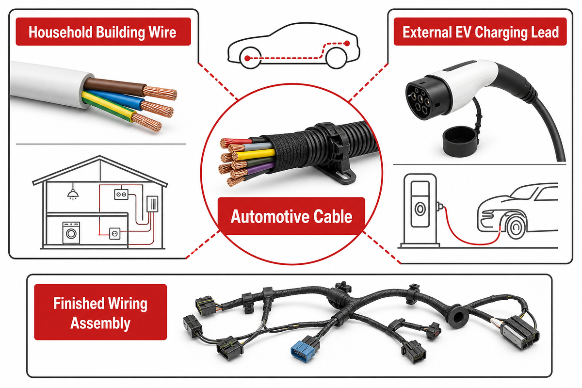
Automotive cable is the conductor-and-insulation system assigned to a defined electrical path in a road vehicle. Some constructions include fillers, screens, braids or outer jackets. The cable remains one component: a finished wiring harness also includes terminations, connectors, protection, branches, labels, support hardware, and a released route.
“This document defines terms in the field of cables applied in road vehicle general purpose applications.”
This definition establishes three boundaries. The household building wire is designed to be installed and tested in a different way. An external EV charging lead is at the interface of the vehicle and the supply, not in the vehicle’s route. The finished wiring assembly is an integrated system and not a substitute for cable within it.
Borders are important because search results combine all four objects. If we don’t state the physical path, a request for “automotive wire” can return primary wire, battery cable, traction cable, speaker wire, charging assembly or a complete loom. Therefore, start the brief with source, load, path, function, then decide the category.
ISO 19642-1:2023 is a 27-page vocabulary and design-guidance document for road-vehicle cable applications. Its public scope gives teams a shared language, but a standard title cannot approve a supplier model, a terminated assembly, or an installed vehicle. Those decisions need their own evidence and named owner.
2. The Main Types of Automotive Cable
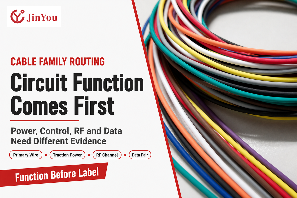
The correct cable type follows the job of the circuit. Primary wire serves many low-voltage point-to-point circuits, battery cable carries high current either near the starting or the low-voltage energy system, traction cable carries high voltage and power, and control or data paths with various transmission requirements are served by multicore, coaxial, twisted-pair, and single-pair constructions.
| Category | Circuit question | Construction clue | Evidence to request | Do not confuse with |
|---|---|---|---|---|
| Low-voltage primary wire | Is this a body, lighting, control, or auxiliary feed? | Flexible stranded conductor with vehicle-grade insulation | Exact standard part, temperature class, fluid and abrasion tests | Building wire |
| Battery cable | Does the path carry starting or low-voltage energy-system current? | Large conductor and termination-focused design | Resistance, crimp, terminal-temperature, corrosion and flex evidence | Signal wire |
| Multicore or control cable | Must several low-power circuits share one sheath? | Multiple insulated cores, fillers and outer jacket | Core identity, separation, bend and jacket tests | A complete harness |
| High-voltage traction cable | Does the path connect traction-energy equipment inside the vehicle? | Defined insulation system, identification and possible screen | Voltage class, thermal duty, route, termination and vehicle tests | External charging lead |
| Coaxial RF cable | Does the path carry an RF signal with a specified bandwidth? | Controlled geometry with inner conductor and screen | Impedance, attenuation, bandwidth, connector and channel results | Generic shielded power cable |
| Twisted-pair data cable | Does the network need a balanced data channel? | Controlled pair geometry, screened or unscreened | Channel loss, balance, EMC and connector results | Two ordinary wires twisted during assembly |
| Single-pair Ethernet cable | Does the in-vehicle link use a defined BASE-T1 channel? | Controlled balanced pair with connector-specific geometry | Impedance, insertion loss, return loss, balance and channel results | Generic twisted hookup wire |
| Charging-inlet internal cable | Is the path inside the vehicle between the inlet and charging equipment? | Power, control, shielding and routing selected for the vehicle side | Interface definition, voltage class, thermal and installed-system tests | Detachable supply-side charging cord |
| Sensor or specialty cable | Does the sensor need a defined low-noise or environmental construction? | Circuit-specific core, screen, jacket or miniature geometry | Sensor interface, route exposure and assembly test plan | One universal “sensor wire” grade |
Category boundaries are based on the public scopes and test families listed by UL Solutions’ automotive cable testing service.
In SAE-oriented markets, primary-wire designations such as GPT, GXL, SXL and TXL are low-voltage and familiar. However, these aren’t worldwide designations for every road-vehicle cable. In addition, these names are applicable only after the circuit is routed to low-voltage primary wire, and after the construction, test set, standard revision, and the program is defined.
SAE J1128_202508 covers low-voltage primary cable at nominal 60 VDC or 25 VAC or less. That boundary keeps four common market designations in their proper lane: they help compare an SAE-oriented low-voltage family, but they don’t classify traction-power, coaxial RF, or external charging cable.
In automotive wiring applications, automotive primary wire usually means a low-voltage copper or aluminum conductor with PVC or another specified insulation system. A cable connection is still only one element of the automotive electrical system. Labels such as durable, fluid resistant, heavy-duty, high-quality, or reliable do not prove that a construction can withstand a harsh route; durability must come from defined test evidence.
For dashboard or other tight spaces, document bend, heat, fuel, and ignition exposure rather than assuming one construction fits. Infotainment, ADAS, and other communication paths carrying high-frequency signals also need channel and signal-integrity evidence. Split wiring applications by circuit duty before selecting the family. Jinyou’s EV charging cable family overview keeps external charging assemblies separate from vehicle-side cable.
3. Map the Cable to the Vehicle Architecture
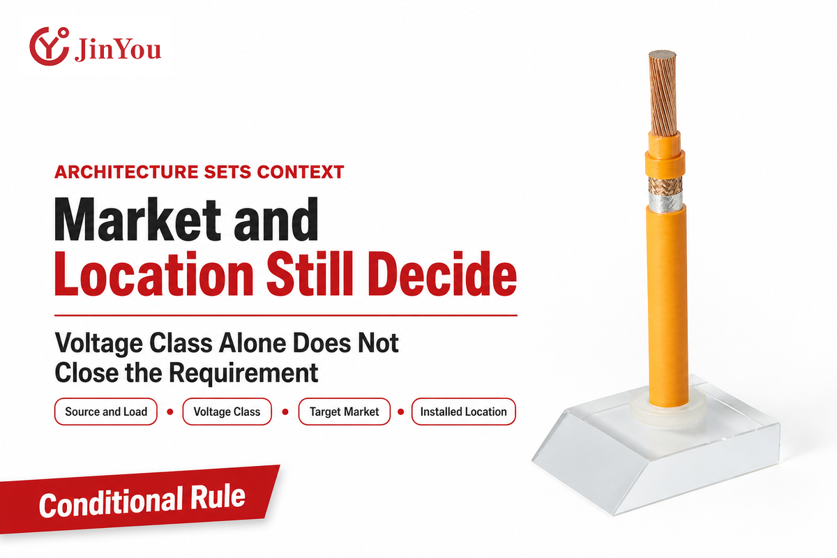
Narrowing the search further, vehicle architecture provides some help, but is incomplete. Capture details of the energy or signal domain, source and load, operating voltage range, current or bandwidth, grounding, route, and target market. A 12 V auxiliary feed, 48 V subsystem, traction-power path, and Ethernet channel need different questions and evidence owners.
| Domain | Primary design question | Likely evidence owner | Boundary |
|---|---|---|---|
| 12 V or 24 V body circuit | Can the path meet voltage-drop, thermal and route limits? | Electrical distribution and harness engineering | Do not select from fuse value alone |
| 48 V subsystem | Which working and abnormal conditions apply at this interface? | System owner plus electrical distribution | The 48 V label does not set conductor area |
| Traction-power path | How do voltage, current duty, switching, heat and route interact? | High-voltage system, EMC and vehicle integration teams | Keep external charging cable separate |
| Control network | What channel behavior must survive the installed route? | Network and EMC teams | Conductor continuity is not channel proof |
| RF or high-speed data | Which impedance, loss and bandwidth targets govern the link? | Signal-integrity, connector and EMC teams | Shield construction alone is incomplete |
Market rules must have priority. In the USA, 49 CFR 571.305 S5.4.1.2 requires orange outer covering for cables from high-voltage sources when those cables are not within electrical protection barriers. The color requirement only applies to the installation situation. Hence, saying “high-voltage architecture” isn’t sufficient.
A U.S. rule defines a high-voltage source above 60 VDC or 30 VAC and then applies the orange-covering condition by cable location. The lesson here’s that architecture and voltage class impose context, and target market rules and installation geometry can introduce stipulations on the release of vehicles.
For the commercial vehicle-side family, review Jinyou’s EV high-voltage cable range; this guide remains focused on the engineering selection method.
4. How Automotive Cable Standards Fit Together
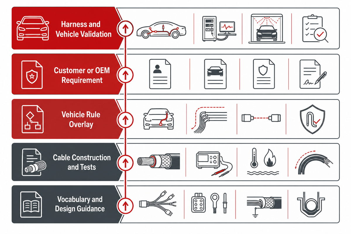
Automotive cable standards work as a stack, not a single approval badge. Construction standards begin with language and design, continue with assembly and test of applicable construction, add target market vehicle rules, then add customer or OEM requirements. The completed assembly and vehicle must show integration evidence with the actual construction and route.
2025-08Current SAE J1128 revision
60 VDCJ1128 nominal DC ceiling
6 GHzISO 19642-11 stated coaxial scope, with 20 GHz special cases
| Level | Question | Example evidence | What it cannot prove alone |
|---|---|---|---|
| 1. Vocabulary and design guidance | Are all teams describing the same cable object? | ISO 19642-1 scope and terms | Exact construction or vehicle release |
| 2. Cable construction and tests | Which part and test methods match this cable family? | ISO 19642-2 plus the applicable product part; SAE J1128 where its scope fits | Target-market installation or final assembly behavior |
| 3. Vehicle rule overlay | Which market, vehicle class, date, and installation condition apply? | Current government rule and applicability record | OEM release or every cable-level property |
| 4. Customer or OEM requirement | What extra limits, specimens, or reports does the program require? | Controlled customer specification and deviation record | A result for an untested construction or route |
| 5. Harness and vehicle validation | Does the terminated, routed system meet release criteria? | Assembly, environmental, electrical, EMC and vehicle reports | Future builds without production identity |
The official ISO 19642-2:2023 catalogue says the document defines test methods used by other parts of the series. That is a clean scope statement: it supports how a cable is tested, but the applicable product part and construction identity still have to be named.
ISO 19642-2:2023 contains 88 pages of test methods used across its cable series. A result that passes the test method is restricted to a specimen and test scope; it does not automatically extend to another insulation wall, conductor, sheath, termination, route, or complete vehicle.
5. Build the Circuit-to-Cable Duty Envelope
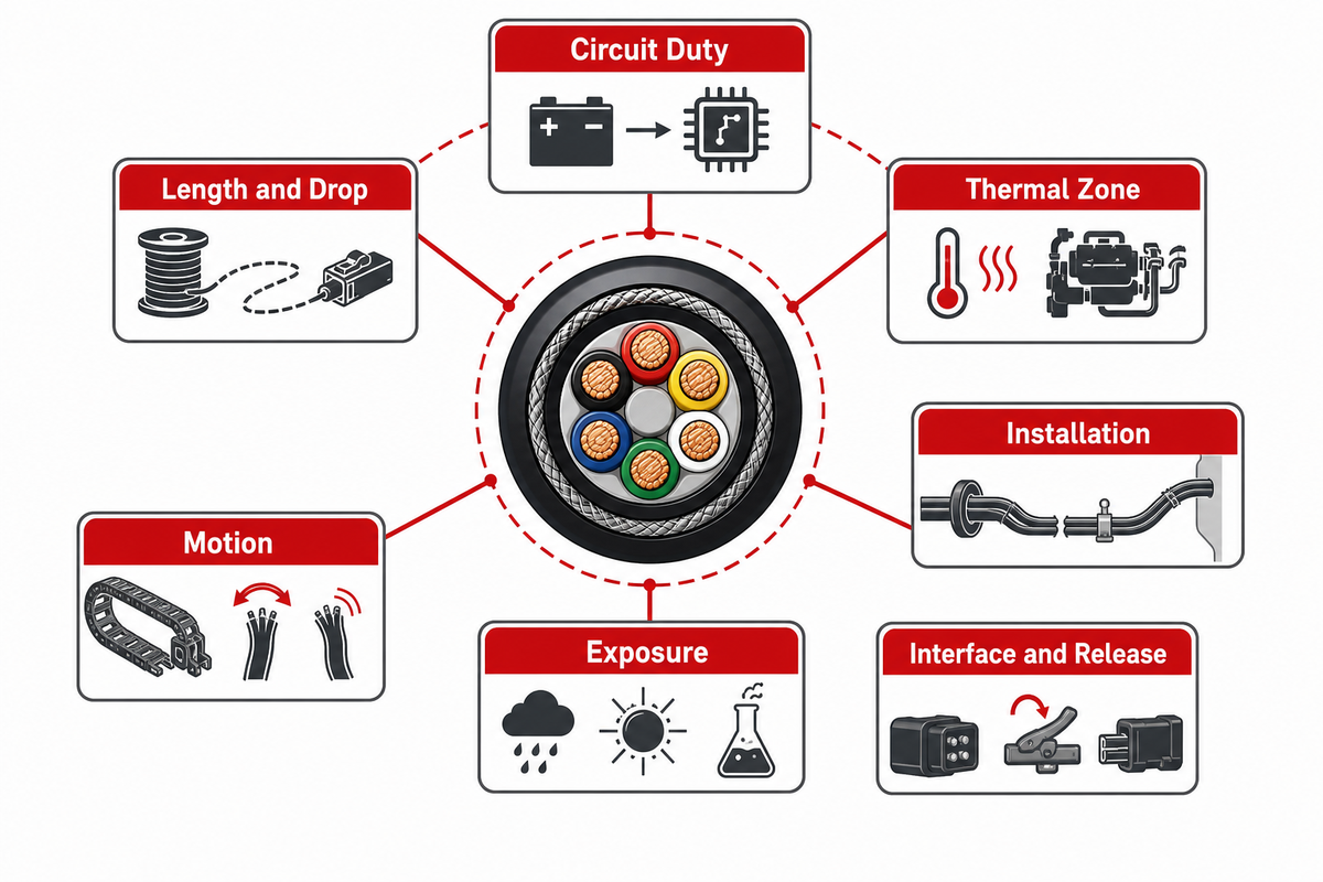
The Circuit-to-Cable Duty Envelope is the minimum information set from which a conductor area determination or material selection can be made. Record current in A, voltage in V, conductor area in mm², one-way route length in m, allowed drop in mV or %, ambient and local temperature in °C, bend radius in mm, and signal range in Hz, MHz, or GHz where applicable. For formatting only, an illustrative record might read 12 V nominal, 20 A continuous, 30 A for 10 sec, 2.5 mm² conductor area, 3 m one-way length, 300 mV allowed drop, 85 °C local temperature, 40 mm minimum bend radius, and a 100 MHz signal limit. These are not cable recommendations. Missing inputs stay visible instead of being hidden behind a familiar gauge.
| Input group | Value to record | Why it changes the decision | Evidence owner |
|---|---|---|---|
| Circuit duty | Working voltage, continuous and peak current, duration, repetition | Sets electrical stress and heating profile | Circuit or system engineer |
| Length and drop | Source-to-load path and allowed voltage loss | Links resistance to circuit performance | Electrical distribution owner |
| Thermal zone | Ambient, local heat, cooling state and exposure time | Changes conductor and material temperature | Thermal and packaging teams |
| Installation | Bundle, conduit, enclosure, clips and nearby circuits | Changes heat rejection and interaction | Cable packaging owner |
| Motion | Static bend, repeated flex, torsion and assembly movement | Changes stranding, diameter and flex evidence | Mechanical integration owner |
| Exposure | Fluids, abrasion, contamination and cleaning agents | Changes insulation, jacket and protection needs | Materials and route owners |
| Interface and release | Terminal, connector, target market, tests and records | Prevents cable-level evidence from being mistaken for system release | Connector, quality and vehicle teams |
Consider two illustrative 20 A circuits. Circuit A is a short run to a cabin and has low ambient temperature and a small bundle. Circuit B is a longer run in a location that is close to a heat source and is in a bundled environment. Current is equal, yet resistance, voltage drop, conductor temperature, material exposure, and route protection don’t share the same boundary. One universal 20 A gauge answer would erase the facts that separate them.
Record before selection
- Measured or modeled duty profile
- Released route length and thermal zone
- Bundle and enclosure condition
- Terminal and connector limits
Do not substitute
- Fuse size for continuous current
- Gauge chart for installed temperature
- Voltage label for insulation evidence
- Static bend statement for flex life
The envelope isn’t a calculator. Selecting a cable for a vehicle is an engineering exercise that combines multiple variables, program constraints, and measured data. After the inputs have been defined, a formula can be used to determine resistance or voltage drop; however, engineering still has to decide which thermal zone, motion cycle, market rule, or vehicle test applies.
6. Read Construction From Conductor to Shield
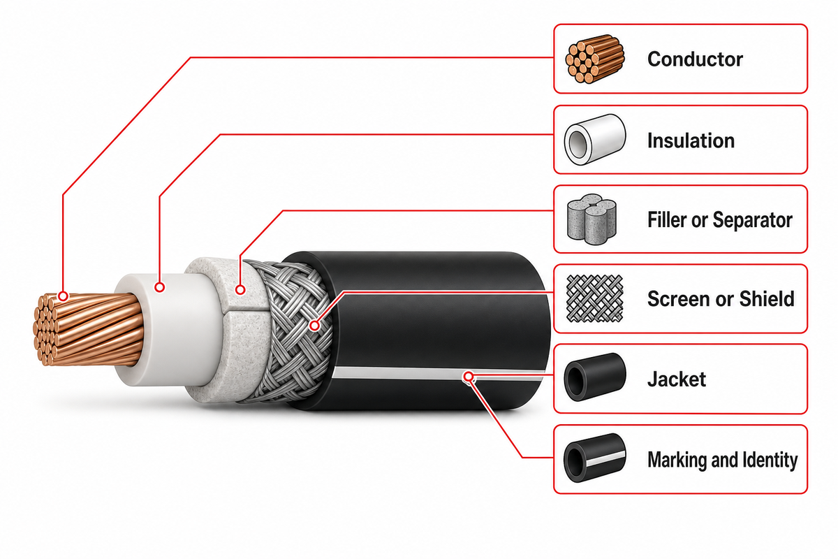
Each cable layer can be interpreted as a function, limit, or proof request. The conductor carries current or signal; insulation supplies the primary dielectric barrier; fillers manage geometry; a screen controls coupling where needed; the jacket faces the route. Marking ties the construction that will be tested to production and subsequent inspection.
| Layer | Function | Failure if misapplied | Proof to request |
|---|---|---|---|
| Conductor | Carry current or preserve the intended signal path | Excess loss, heat, stiffness or fatigue | Material, cross-section, stranding, resistance and flex data |
| Insulation | Provide dielectric separation around each conductor | Cracking, softening, chemical attack or dielectric breakdown | Exact material system, wall, aging and electrical tests |
| Filler or separator | Control geometry and isolate layers | Poor roundness, pressure points or unstable pair geometry | Cross-section, material identity and process control |
| Screen or shield | Control electromagnetic coupling and carry intended shield current | Noise, discontinuity, flex damage or poor termination | Construction, transfer behavior, continuity and connector interface |
| Jacket | Protect inner layers from the installed route | Abrasion, swelling, cracking or assembly damage | Fluid, heat, abrasion, flame and marking tests |
| Marking and identity | Connect cable, lot, drawing and test record | Evidence cannot be tied to the supplied reel or build | Lot trace, print content, drawing revision and change control |
Coaxial RF cable places geometry and behavior of transmission in the foreground. ISO 19642-11:2023 names a specified analogue bandwidth up to 6 GHz, with 20 GHz special cases. Consequently, a description of the shield and conductor is incomplete without impedance, attenuation, connector, and channel evidence.
The termination of a shield must be examined on its own. In their NIST Technical Notes on the Protection of Electronic systems, the cable-shield termination through connectors is considered part of the bonding issue. In a vehicle, the final verdict still comes from the applicable component, terminated assembly, and installed-system test plan.
ISO 19642-11:2023 defines coaxial RF cable by analogue bandwidth up to 6 GHz, with 20 GHz special cases. A braid or foil can be described correctly while the terminated channel still lacks the required transmission evidence.
7. Routing and Harness Integration Change the Requirement
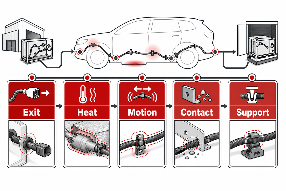
A cable that passes component tests can still be adversely affected by the route in which it’s installed. Bend transitions, repeated motion, heat sources, sharp edges, clamps, connector exit angle, service loops, assembly tools, and branch points all cause stress to be redistributed. For this reason, cable selection depends on the route and can’t be treated as a drawing afterthought.
A five-point route audit begins at the source and follows the cable to the load:
- Exit: Check connector back-shell direction, strain relief, sealing, and first bend.
- Heat: Mark local sources, hot surfaces, cooling states, and heat-soak periods.
- Motion: Separate assembly movement, vehicle motion, door or seat cycles, engine movement, and service handling.
- Contact: Find edges, brackets, fasteners, moving parts, fluids, and debris paths.
- Support: Review clamp type, support logic, branch restraint, service loop, and inspection access.
An official NHTSA recall report provides a bounded example: An improperly secured wiring harness could contact the A/C compressor pulley. The takeaway isn’t a generic clamp spacing. The takeaway is that support, clearance, and relative movement can determine the outcome even with the cable material selected.
Don’t intermingle static bend radius and repeated-flex life. A cable can fit around one bend during assembly yet fail when that bend moves through thousands of cycles or when the connector exit concentrates strain. Request evidence that matches the motion mode, temperature, specimen, termination, and cycle definition instead of extrapolating from a one-time installation statement.
8. Build a Validation Evidence Chain
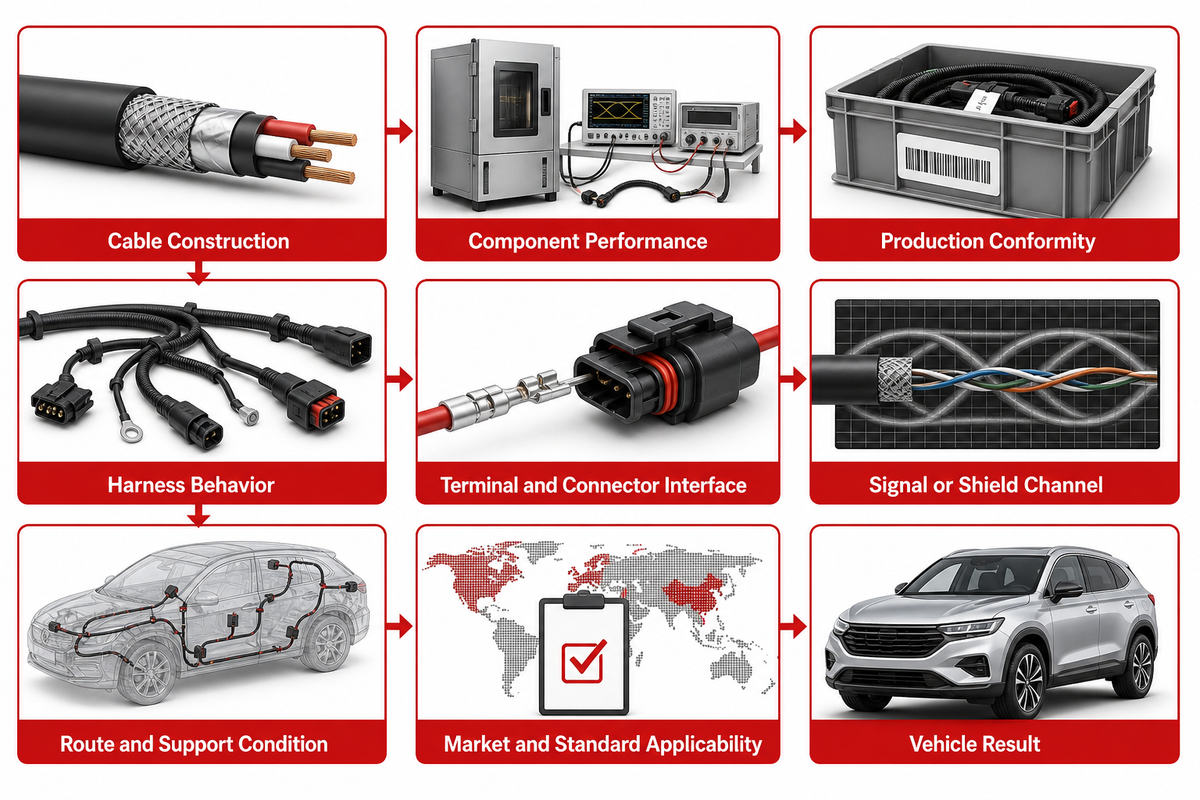
Each claim needs a documented release chain that begins with the published data sheet and type-test evidence for the exact construction and production trace, then identifies the specimen, build identity, owner, and decision. The terminated assembly and installed vehicle are verified. Target-market rules sit alongside this chain because applicability depends on the vehicle and installation.
Jinyou’s quality testing and traceability overview provides the commercial document-control context; the matrix below explains how to audit evidence without treating one certificate as vehicle approval.
1 — Published definition
The data sheet names the offered construction, ratings, dimensions and referenced standards.
2 — Exact-construction test
A report identifies the specimen, method, condition, result and revision.
3 — Production identity
Lot, reel, drawing and change records connect the delivered cable to tested construction.
4 — Terminated harness
Crimps, connectors, screens, seals, branches and protection are checked as an assembly.
5 — Installed vehicle
Electrical, environmental, route, EMC or channel tests decide release in the intended vehicle context.
| Claim | Evidence | Specimen identity | Owner | Release decision |
|---|---|---|---|---|
| Cable construction | Controlled drawing and data sheet | Part, revision, material and dimensions | Cable design | Candidate construction defined |
| Component performance | Type-test or qualification report | Test sample and method | Test or quality team | Scoped result accepted |
| Production conformity | Lot, reel and process records | Delivered build | Manufacturing quality | Delivery linked to approved design |
| Harness behavior | Crimp, connector, seal, screen and route tests | Terminated assembly | Harness and connector teams | Assembly accepted |
| Terminal and connector interface | Crimp section, pull, sealing and contact checks | Released terminal-cable pair | Connector engineering | Interface accepted |
| Signal or shield channel | Impedance, loss, balance, bonding or EMC report | Terminated channel | Signal-integrity and EMC teams | Channel target accepted |
| Route and support condition | Clearance, clamp, heat, motion and abrasion review | Released route geometry | Vehicle packaging | Route risk accepted |
| Market and standard applicability | Rule, edition, scope and deviation record | Vehicle market and build date | Compliance owner | Applicability confirmed |
| Vehicle result | Installed electrical, environmental, EMC or channel report | Vehicle build and route | Vehicle program | Program release |
Don’t provide marketing language to fill in a missing layer. A certificate with only a logo and no exact part or scope isn’t a test report. A generic report that has no construction identity can’t be assigned to the offered cable. A current component result doesn’t justify a modified termination or route. Negative evidence, wrong edition, different specimen, or missing applicability, must remain visible until resolved.
UL reports automotive cable testing from -40 °C to 125 °C for many applications and up to 250 °C in some cases. Those figures describe the span of its test services, not one cable’s rating. The exact specimen, construction, method, exposure, and acceptance result still govern a release decision.
9. Use the 7-Field Automotive Cable Selection Record
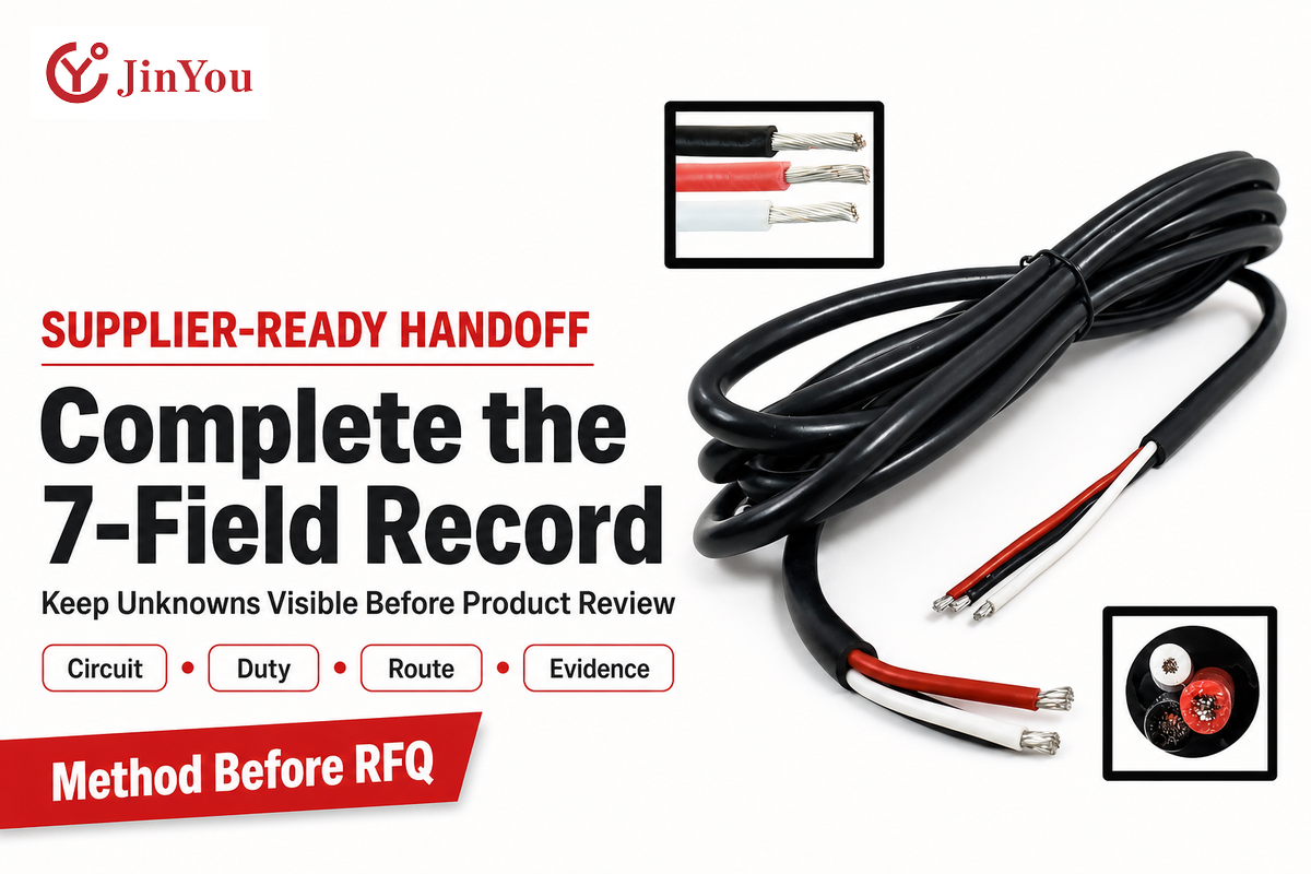
The 7-Field Automotive Cable Selection Record converts an ambiguous request into a reviewable handoff. It includes the circuit and architecture, electrical duty, route length and drop limit, environmental exposure, motion and routing, construction and termination, as well as the target market and validation evidence. Other relevant unknowns are left open rather than replaced by guesses.
| Field | Record | Review question |
|---|---|---|
| 1. Circuit and architecture | Source, load, power/control/data role and vehicle domain | Are all teams specifying the same physical path? |
| 2. Electrical duty | Working voltage, current or bandwidth, peaks, duration and abnormal conditions | Which value controls design and which controls test? |
| 3. Length and loss | Released path length, return path and allowed voltage or signal loss | Has the full channel been counted? |
| 4. Environment | Ambient, local heat, fluids, contamination and abrasion | Which exposure is continuous, cyclic or accidental? |
| 5. Motion and routing | Bends, repeated flex, torsion, clamps, edges and service access | Does the evidence match the real motion mode? |
| 6. Construction and termination | Conductor, insulation, screen, jacket, terminals and connector interface | Can each layer be tied to a required function? |
| 7. Market and evidence | Target market, applicable vehicle rule, standard edition, test matrix and release owner | What proves the exact offered build is acceptable? |
When these fields are completed, review Jinyou’s automotive cable solutions for the commercial product-family handoff. The Jinyou Cable Company Background provides the name of the manufacturer; this background isn’t being used as independent evidence of a technical statement.
Selection record takeaway
Do not send a supplier only a cable name and gauge. Send the seven fields, flag open assumptions, request evidence tied to the exact construction, and name who releases the cable, terminated assembly, and installed vehicle.
Send Your Circuit and Environment Details →
Frequently Asked Questions
What type of wire is used in automotive applications?
Automotive applications use several cable families because power, control, sensor, RF, and data circuits do not share one duty, route, termination, validation plan, or release owner.
Primary wire serves many low-voltage circuits, battery cable serves high-current low-voltage paths, high-voltage cable connects traction equipment, and coaxial or twisted-pair designs carry RF or data. The final choice follows voltage, current or bandwidth, route, temperature, fluids, motion, termination, and the applicable test plan. The exact construction and evidence must match the installed circuit.
What is the difference between automotive cable and household cable?
Automotive cable is selected for vehicle vibration, routing, temperature, fluids, compact packaging, terminations, and vehicle evidence; household cable follows a building-installation framework with different codes, test assumptions, and installation rules.
The difference isn’t one material or one strand count that applies to every product. It’s the complete design and test context. Vehicle cable must be matched to the circuit and installed route, while building wire is evaluated under its own codes, installation methods, and environmental assumptions. Never substitute one category from gauge alone.
Is automotive wire the same as a wiring harness?
No. Cable is a component; a wiring harness is the routed assembly built from cables, terminals, connectors, branches, protection, labels, and support hardware, so cable, assembly, and vehicle evidence have different owners.
This distinction changes evidence ownership. Cable-level tests address a defined construction and specimen. Assembly validation adds crimps, seals, connector interfaces, branches, screen termination, clips, abrasion protection, and routing. Vehicle tests then assess the installed assembly in its final electrical and environmental context. Each level therefore needs its own specimen identity and release owner.
Which standard applies to automotive cable?
The applicable standard depends on cable type, voltage band, conductor, construction, signal function, market, and vehicle-program requirement; no single document approves every cable, harness, route, or installed vehicle.
Start with the exact document and edition, then read its public scope before citing it. ISO 19642 separates vocabulary, test methods, and cable-family requirements. SAE J1128 covers a defined low-voltage primary-cable scope. Neither reference settles every cable family or market. Next identify the applicable target-market vehicle rule, OEM specification, and customer release requirement. Then map each requirement to the offered construction, the actual report specimen, its revision, and its production trace. Termination, connector sealing, screen bonding, routing, thermal interaction, and installed EMC or channel behavior may require separate assembly and vehicle tests. A standard number on a data sheet is useful evidence, but it never replaces this applicability chain.
How do you choose automotive cable size?
Choose conductor area from a defined duty envelope, not from current or fuse size alone, then verify voltage drop, conductor temperature, terminal limits, motion, bundling, cooling, and the released route.
Record continuous and peak current, route length, voltage-drop limit, heat, bundling, terminal limits, motion, and cooling. Calculate a candidate, then validate the installed result.
Does shielding guarantee EMC performance?
No. Shield construction is one input; termination, connector bonding, grounding, routing, noise spectrum, and installed-system tests determine the result, so the complete electromagnetic path must be validated as a terminated channel.
A coverage percentage or braid material can’t represent the complete electromagnetic path. Data and RF cables also need impedance, loss, bandwidth, balance, and channel evidence. Define the circuit’s EMC or transmission target first, then verify the terminated assembly and vehicle route against the applicable acceptance plan.
The Final Check Before Release
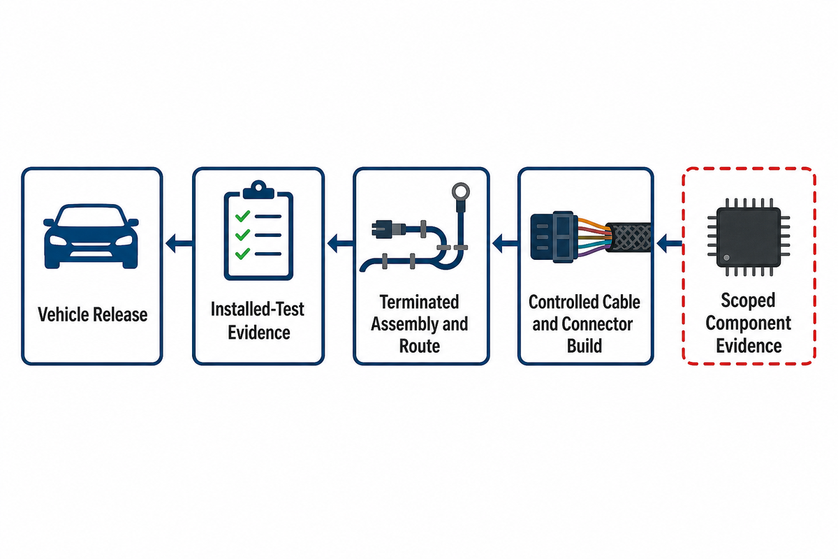
Good automotive cable decisions can be audited backward. A vehicle release should point to installed-test evidence. That test points to a terminated assembly and route. The assembly points to a controlled cable and connector build. That build points to scoped component evidence. Any missing link leaves a gap in that chain.
The nine decisions in this guide aren’t nine product filters. They’re ownership checks. Define the object, route the cable family, map the architecture, read standards by scope, build the duty envelope, inspect the build, review the routing, assemble the evidence chain, and send a complete selection record. That process protects both engineering quality and search intent: the guide teaches the method, while the product page handles the commercial review.
How This Guide Was Checked
The guide separates automotive cable selection from product-family sales content. Its standards, vehicle-rule, route, and signal-function claims were traced to current public ISO, SAE, UL, NHTSA, eCFR, university, and NIST sources; supplier pages were used only for identity and the commercial handoff. Reviewed by the Shanghai Jinyou Jinhong Intelligent Electric Co., Ltd. technical team.
References & Sources
- International Organization for Standardization, ISO 19642-1:2023
- International Organization for Standardization, ISO 19642-2:2023
- SAE International, J1128_202508 Low Voltage Primary Cable
- UL Solutions, Automotive Cable Safety and Performance Testing
- eCFR, 49 CFR 571.305, S5.4.1.2
- International Organization for Standardization, ISO 19642-11:2023
- NHTSA, Part 573 Safety Recall Report 21V-534
- Federal Register, FMVSS No. 305a Final Rule Record
- University of New Hampshire InterOperability Laboratory, MultiGBASE-T1 Automotive Ethernet
- National Institute of Standards and Technology, Protecting Electronic Systems