Get in touch with JINYOU Cable Company

-
CALL US +86 181 1623 2461
-
EMAIL sales@jinyougroup.cn
JINYOU Cable
PV Control Cable for Solar Monitoring and Protection Circuits
Application Scope
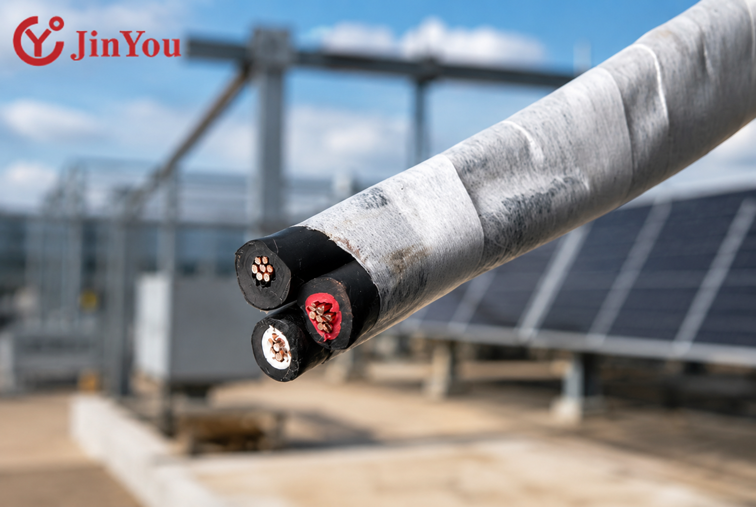
Solar control cable for multi-core control-loop signals, monitoring, protection and auxiliary wiring in photovoltaic systems. This family is separate from the single-core direct-current power cable that runs from a solar panel string to an inverter.
Construction Details
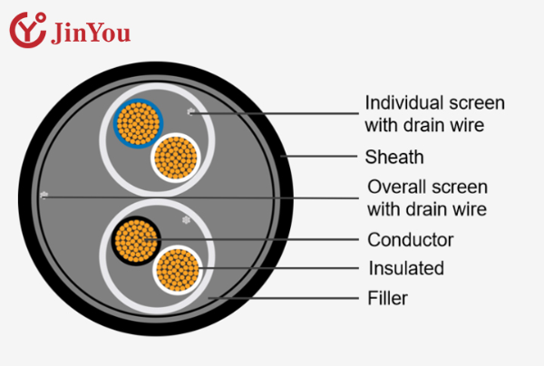
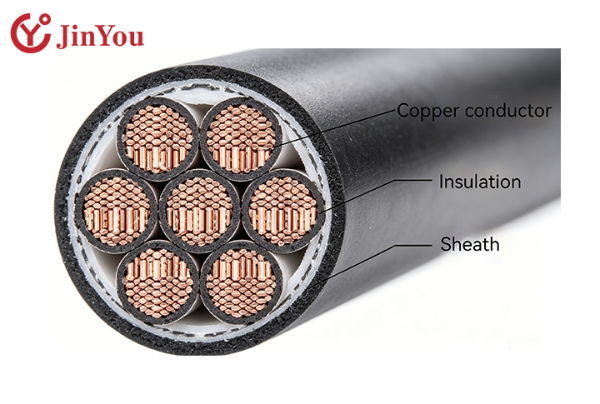
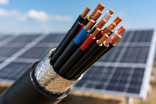
Jinyou lists 450/750 V, 2.5–10.0 mm² conductor cross-sections and 2–61 cores, with cross-linked polyolefin insulation and a thermoplastic elastomer sheath. Shielded and armored constructions are reviewed against the route and the circuit, not selected from core count alone.
450/750 V
Rated voltage listed
2.5–10.0 mm²
Conductor cross-section
2–61
Core-count range
125°C
Maximum operating-temperature label
−40°C to 90°C
Environmental-temperature label
100–1000 m
Roll and plastic-drum options
Control, Monitoring and Protection Circuit Capabilities
The cable family serves signal and protection circuits between devices in a photovoltaic power system. Use the solar control cable for equipment-to-equipment control loops, monitoring or auxiliary circuits, and protection circuits that need a defined multi-core route.
Send the circuit class, equipment endpoints, voltage, current and protective-device context before construction is confirmed. A tracker motor, a position sensor, a relay and a controller may sit in different endpoint groups; treating them as one undifferentiated solar wire creates avoidable selection risk.
Search results also surface a charge controller, battery wiring and AWG extension wire. Those adjacent terms describe other routes; they do not turn this solar photovoltaic control cable into a direct-current power lead.
Selection starts with the wiring system and its endpoints, not with a cable label.
Control-loop signals
Map each core to the controller, relay, actuator or tracker interface. Include the signal type and the equipment manual’s termination requirements.
Monitoring and auxiliary signals
Identify sensors, data acquisition, alarms and auxiliary power separately. State whether the route is fixed, moving or exposed to switching noise.
Protection circuits
Describe the protective device, fault context and required conductor arrangement. Protection wiring is reviewed with the system designer rather than inferred from the cable name.
Engineering note grounded in IEC 60364-5-52:2009
A multi-core control cable is easily confused with a solar direct-current power lead when a search starts with the word “solar.” A shield choice does not finish the electromagnetic-compatibility design, and the termination plan remains part of the circuit review.
Control cable and PV direct-current power cable serve different routes
| Route decision | PV control cable | PV direct-current power cable |
|---|---|---|
| Primary job | Multi-core control, monitoring, protection and auxiliary signals | Direct-current power transfer from module strings toward electrical conversion equipment |
| Product range on this page | 450/750 V; 2.5–10.0 mm²; 2–61 cores | Use the applicable photovoltaic power-cable family and its scoped rating |
| RFQ input | Endpoints, signal class, shielding, bonding, armoring and packaging length | String current, voltage, ampacity, connector system and direct-current route |
| Fit boundary | These families are not interchangeable; the wrong answer is to infer a power-cable selection from a control-cable core count. | Use the cable type that matches the circuit’s actual job. |
Construction Options for Outdoor and Interference-Prone Routes
Cross-linked polyolefin insulation and a thermoplastic elastomer sheath form the listed base construction. The product page also labels moisture and salt-fog protection, ultraviolet radiation and ozone resistance, while the route review separates environmental exposure from electromagnetic and mechanical decisions.
Environmental exposure
- Record outdoor, humid or salt-fog exposure.
- Confirm the project temperature envelope and the document basis for any rating.
- Include ultraviolet radiation (UV), ozone, pressure, tensile and animal-bite exposure where those risks apply.

Shielding, bonding and termination
- State the signal type and nearby switching equipment.
- Define the shield construction, termination points and bonding plan with the equipment manual.
- Do not assume a shield removes noise when ground-potential differences can drive shield current.
Armoring and mechanical route
- Review tray, conduit, exposed and equipment routes for abrasion or impact.
- Model movement, bend and maintenance access before selecting an armored reference.
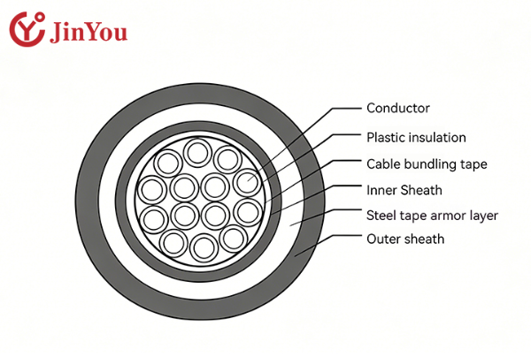
- Reference models include GF-WDZX(N)KEE(R)P and GF-WDZX(N)KEE23; exact construction mapping is confirmed in the project file.
System-level lightning boundary
Armor addresses a mechanical route; shielding and bonding address interference; neither replaces the coordinated surge-protection measures described by IEC 62305-4:2024. The project electrical design must coordinate lightning electromagnetic impulse protection, equipment bonding and cable routing.
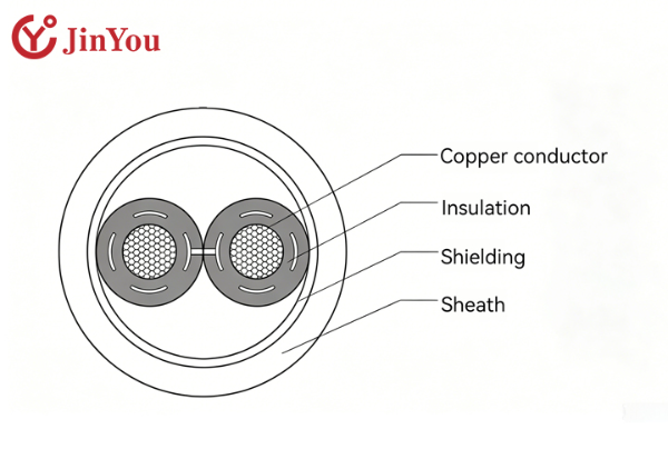
Outdoor reliability is also an installation-quality problem. The root cause of a route mismatch is often that voltage, current, grouping and termination were never recorded before a 450/750 V, 2.5–10.0 mm², 2–61 cores family was discussed; Jinyou uses the project inputs to close that gap under IEC 60364-5-52:2009.
Do not substitute a generic PVC jacket or an unscoped UL mark for the construction and documents requested in the project file. A high-quality review names the material, test basis and route rather than relying on a label.
Submit Project File & Route Inputs
Direct technical review for engineers, EPC contractors & OEM project partners.
PV Control Cable Specifications
The table keeps the exact product-page labels visible and marks the two temperature entries as labels that need project confirmation. They are not converted into an unstated continuous conductor rating.
Nominal voltage and core count are not enough for conductor selection. Temperature labels without a basis can be misread as a design rating, so the duration, conductor condition and test basis stay in the review record.
| Parameter | Listed value or range | Project review note |
|---|---|---|
| Rated voltage | 450/750 V | Confirm circuit class and protective-device context. |
| Conductor cross-section | 2.5–10.0 mm² | Size against current, length, grouping and permissible voltage drop. |
| Number of cores | 2–61 cores | Map each core to a named endpoint and termination. |
| Insulation | Cross-linked polyolefin insulation | Confirm the required document and test scope for the order. |
| Sheath | Thermoplastic elastomer sheath | Review outdoor, moisture, ozone and mechanical exposure. |
| Maximum operating-temperature label | 125°C | Duration, conductor condition and test basis must be confirmed for the project. |
| Environmental-temperature label | −40°C to 90°C | Do not treat this as a continuous conductor rating without scoped data. |
| Model references | GF-WDZX(N)KEE(R)P; GF-WDZX(N)KEE23 | Final model and construction follow the reviewed circuit and route. |
| Packaging | 100 m or 200 m rolls; 100 m, 500 m or 1000 m plastic drums | State pull length, drum handling and site receiving constraints. |
Check a Configuration for Your Project
Open the cable configuration checkConfiguration Matrix by Route and Interference Risk
This selection matrix turns an RFQ into an engineering review path. It does not output an automatic model or a safety conclusion; it makes the inputs visible before the cable construction is confirmed.
| Buyer input | Decision to confirm | Page output |
|---|---|---|
| Control, monitoring, protection or auxiliary circuit | Specified circuit class, function and equipment endpoints | Circuit grouping and core mapping |
| Circuit voltage and current | Electrical loading and protection context | Engineering review input; not an automatic cable-size answer |
| Run length and permissible voltage drop | Resistance budget and acceptable loss | Required conductor data and calculation path |
| Required conductor class or resistance | Flexibility, termination and electrical requirement | Construction review |
| Cable tray, conduit, equipment or exposed route | Mechanical and installation constraints | Sheath, flexibility and armoring review |
| Inverter, tracker, relay or auxiliary equipment area | Electromagnetic environment, shielding and bonding | Shielding and termination review |
| Humid, salt-fog or outdoor exposure | Environmental risk | Material and test-document review |
| Ambient, grouping and installation method | Thermal and routing constraints | Project-specific rating review |
| Termination arrangement and packaging length | Termination compatibility and delivery plan | Roll or drum plan |
Why the input list matters
IEC 60364-5-52:2009 treats wiring-system selection, cable sizing and maximum permissible voltage drop as engineering inputs. A core count by itself cannot establish ampacity, voltage-drop compliance or a suitable termination.
Tracker wiring connects different endpoint classes: motors, position sensors and controllers may have different signal and protection requirements. The wrong choice is to flatten those endpoints into one assumed cable function.
Quotation, Lead Time and Commercial References
Price follows the circuit construction, conductor cross-section, core count, shielding or armoring, packaging, quantity and the documents required for release. There is no fixed retail price list for a project-specific solar control cable; the confirmed figure returns in a written quotation after specification review.
Active Variables
Inputs that move the quotation
Material and conductor
Commercial effect
Changes material value and processing route
Useful RFQ detail
Cross-section, conductor class and resistance requirement
Core map and signal mix
Commercial effect
Changes construction complexity and test plan
Useful RFQ detail
Endpoint schedule and core identification method
Shielding or armoring
Commercial effect
Adds construction and termination review
Useful RFQ detail
Interference risk, bonding plan and mechanical route
Packaging and quantity
Commercial effect
Changes production planning and site handling
Useful RFQ detail
Roll or drum length, quantity and receiving limits
Initial response
Initial inquiries receive an initial response within 24 hours; quotation timing follows specification review.
Production reference
Production runs are scheduled at 25–35 working days, confirmed with your quotation.
Standard production reference
A standard production reference is 10,000 meters; the confirmed MOQ depends on construction and packaging.
Trial orders
Trial orders may be available after specification review; quantity and charges are confirmed in the quotation.
Payment reference
A common reference is 30% T/T in advance, with the balance before shipment; final payment terms are confirmed in the quotation.
Shipment terms
Common shipment references include EXW, FOB, CFR, and CIF; the applicable Incoterm is confirmed in the quotation.
From Circuit Requirements to Packed Cable
-
PROCESS 01
Submit the circuit — provide control, monitoring, protection or auxiliary class, equipment endpoints, voltage, current and protection context.
-
PROCESS 02
Describe the route — state length, permissible voltage drop, installation method, ambient temperature, grouping and bending conditions.
-
PROCESS 03
Confirm the construction — align cross-section, core count, conductor class or resistance, termination, shield, armor, marking and packaging.
-
PROCESS 04
Complete project evaluation — receive cable-selection suggestions and a system-integration solution review.
-
PROCESS 05
Approve the order file — confirm a trial order or production reference, test documents and the commercial terms.
-
PROCESS 06
Pack and ship — release the confirmed roll or plastic-drum length for site receiving.
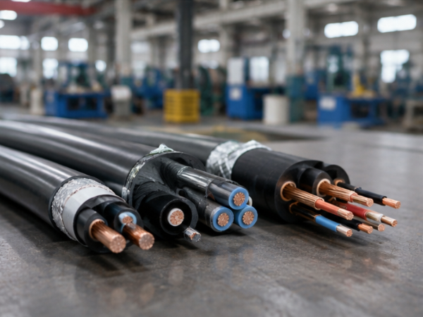
Design notes that reduce avoidable rework
Keep endpoint names and core identification consistent from the schematic to the cable mark. Call out the shield termination and bonding plan instead of leaving it to field interpretation. Give the permitted voltage drop and route grouping before cable sizing is reviewed under IEC 60364-5-52:2009.
We review the submitted circuit and installation inputs before confirming the cable construction in the quotation.
Open the RFQ input checklist
Jinyou Cable Manufacturing for Renewable-Energy Projects
Shanghai Jinyou Jinhong Intelligent Electric Co., Ltd. was established in 2006 and is based in Shanghai. The company designs, manufactures and sells photovoltaic, energy-storage, electric-vehicle and special cable families, supported by automated production machinery and testing systems.
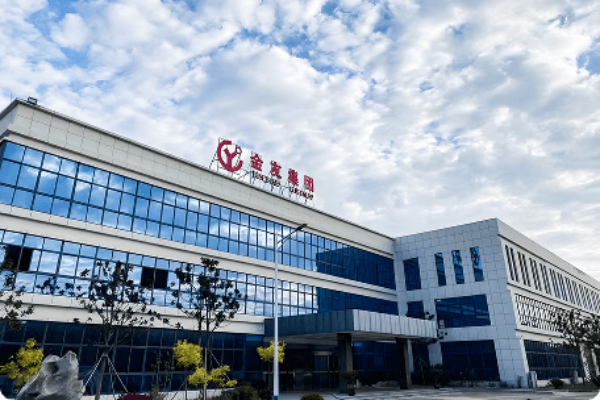
Company-Level Export StatementJinyou’s company information describes supply to more than 40 countries. That is a company-level export statement, not a product-specific service-life, certification or project-savings claim.
Configuration-first performance value
No cable-specific payback, service-life multiplier or failure-rate figure was verified. The defensible value is earlier route, termination and document review, which lowers mismatch and rework exposure before production.
Armor, shielding and surge protection solve different risks. A shield does nothing for an uncoordinated surge-protection design, while armor can still be the right mechanical answer for an exposed route.
When a Different Solar Cable Is the Better Fit
A clear boundary protects the project. The right solar cable depends on the circuit’s job, endpoints, route and document requirements.
| Situation | Why this family is not the first choice | What to do instead |
|---|---|---|
| Module string to combiner or inverter direct-current power | The route transfers photovoltaic power rather than control or protection signals. | Review the applicable H1Z2Z2-K, PV1-F or other direct-current power-cable family. |
| Long-distance, high-speed data communication | The circuit may need a communication cable or fiber architecture with different signal requirements. | Evaluate fiber or a dedicated communication cable before selecting a multi-core control cable. |
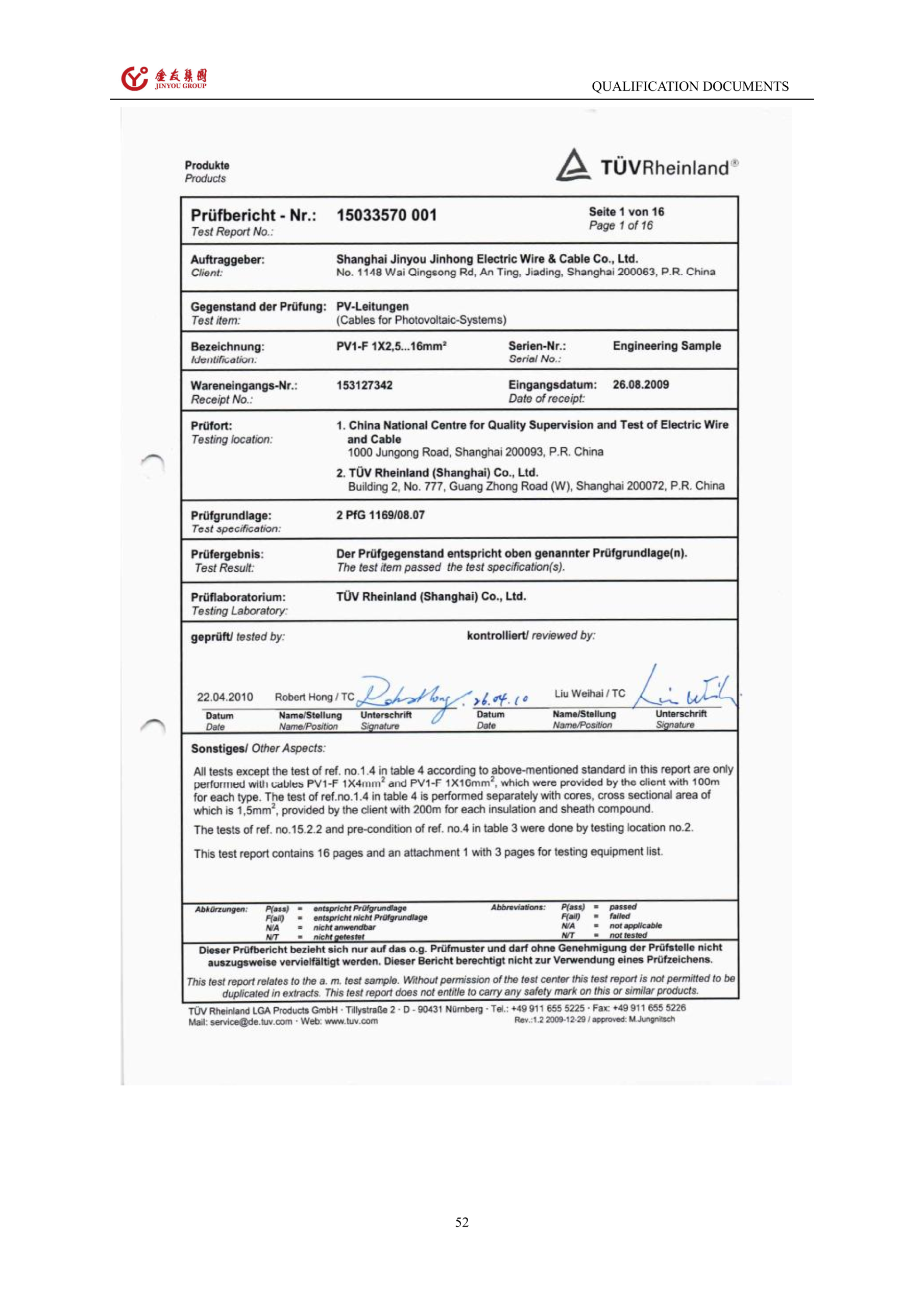
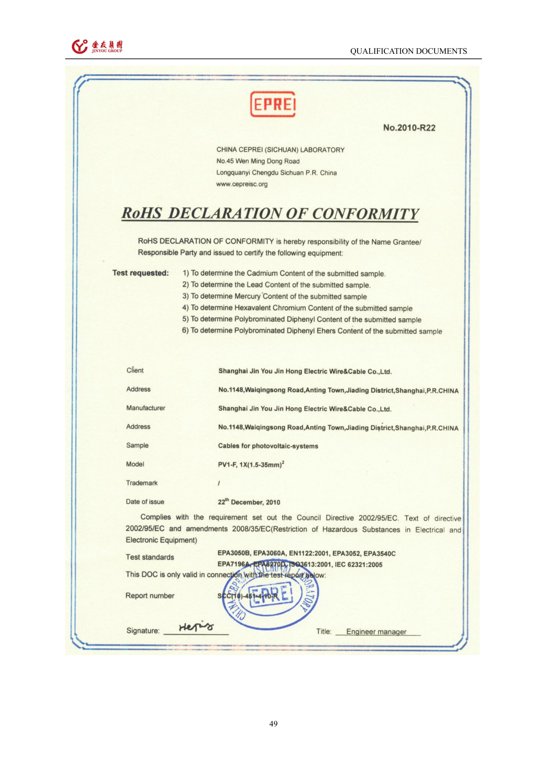
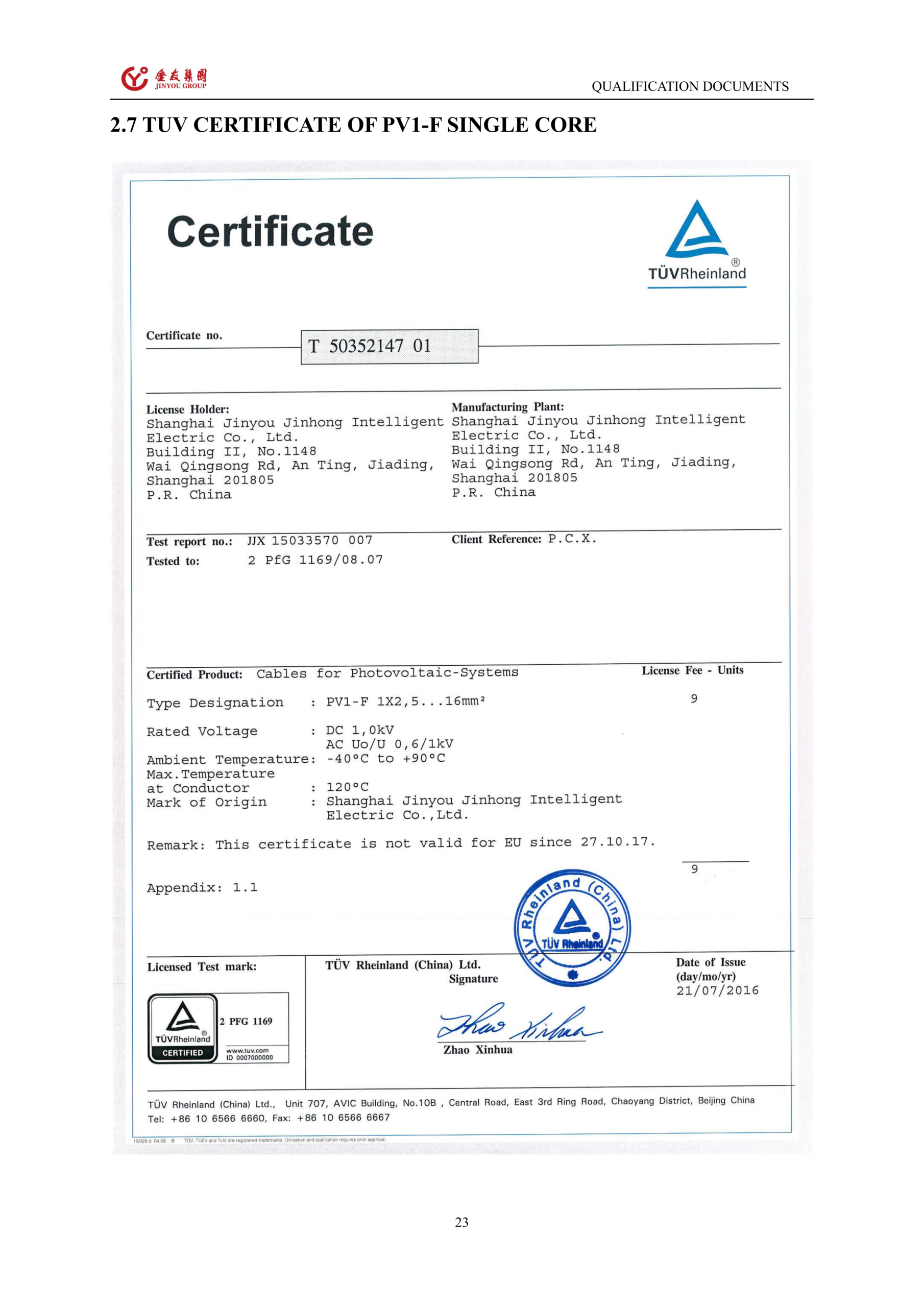
| A specified standard or certificate is required | The exact product page does not name a product-specific standard or certificate number. | Request the model-scoped certificate or test report and confirm its issuer, method and validity for the order. |
| The cable is expected to solve every lightning or noise problem | Shielding, armoring and system surge protection address different risks and are not interchangeable. | Coordinate the termination, bonding and lightning-protection design with the project electrical engineer. |
PV Control Cable Engineering & Sourcing Tools
PV Control Cable Configuration Check
Validate cable specifications against your solar project requirements. Ensure electrical and environmental compatibility.
PV Control Cable Route Risk Matrix
Assess mechanical and environmental hazards along your cable routing. Identify necessary armoring and shielding.
PV Control Cable Test Document Request
Access comprehensive factory testing reports and compliance certificates. Verify our quality assurance protocols.
RFQ Input Checklist
Prepare accurate technical parameters for your request for quotation. Streamline the custom OEM ordering process.
PV Control Cable Questions
What is a PV control cable used for?
It carries multi-core control-loop, monitoring, protection and auxiliary signals inside a photovoltaic power-generation system. The equipment endpoints and circuit class are confirmed before construction is quoted; see the listed Jinyou Cable family for the product context.
How is a PV control cable different from a solar DC power cable?
A control cable connects signal and protection endpoints; a solar direct-current power cable transfers energy from module strings toward conversion equipment. This page’s listed family is 450/750 V with 2–61 cores, not a substitute for every PV wire route.
Which voltage, size and core-count options are available?
The listed range is 450/750 V, 2.5–10.0 mm² and 2–61 cores. Final selection uses current, run length, permissible voltage drop, grouping and installation method under IEC 60364-5-52:2009.
When should shielding be reviewed for a solar control circuit?
Review shielding when the circuit runs near switching equipment, inverter areas, tracker drives or other interference sources. The termination and bonding plan follows the signal type, equipment manual and project electromagnetic-compatibility design.
Does cable armor replace system-level lightning protection?
No. Armor is a mechanical route decision; IEC 62305-4:2024 addresses designed, installed, inspected, maintained and tested surge-protection measures for lightning electromagnetic impulse. The two functions are not interchangeable.
Can this cable be reviewed for humid, salt-fog and outdoor routes?
Yes. The product page labels moisture and salt-fog protection plus ultraviolet radiation and ozone resistance. The project file still needs the temperature envelope, route exposure and the document scope that supports the required construction.
Which electrical and installation details are needed to configure a custom PV control cable?
Send circuit class, endpoints, voltage, current, protective-device context, length, permissible voltage drop, conductor requirement, core map, installation method, grouping, ambient conditions, shield or armor need, termination and packaging length.
Which roll and drum lengths are available?
Listed options include 100 m and 200 m rolls, plus 100 m, 500 m and 1000 m plastic drums. The quotation confirms the length against the route and receiving plan.
Are test reports available for project review?
Jinyou lists photovoltaic-cable test report availability. Ask for the exact model, issuer, test method, date and limitation so the report can be matched to the project requirement.
What are the reference MOQ, lead time and payment terms?
A standard production reference is 10,000 meters; production runs are scheduled at 25–35 working days; a common payment reference is 30% T/T in advance, with the balance before shipment. The quotation confirms the applicable construction, packaging and terms.
Can Jinyou support trial orders?
Trial orders may be available after specification review; quantity and charges are confirmed in the quotation. Include the sample construction, test documents and receiving address in the request.
How quickly will Jinyou respond to an inquiry?
Initial inquiries receive an initial response within 24 hours; quotation timing follows specification review. Send the endpoint and route inputs with the RFQ so the first response can address the actual circuit.