Jinyou Cable · VFD control-cable family

VFD Cable for Variable Frequency Drive Systems

A VFD cable is a power or control cable selected for the voltage stress, switching environment, run length, shielding path and grounding needs of a drive-to-motor circuit. One name covers two different jobs: the power cable that feeds motor current, and the shielded control cable that carries the drive’s signal, sensor and auxiliary circuits along the same route. VFD cable selection starts with the drive output, motor interface, run length and grounding path—not a catalog label alone.

Scope from the source page: Jinyou Cable publishes four silicone-rubber-insulated shield constructions for the second job, with model-bound core, cross-section and temperature data. Its own product page states they are used for controlling weak voltage and current signals in the control circuit of a variable frequency drive, so every model-bound figure below stays inside that scope.

4 named constructions
1–20 cores in the source table
0.75–2.5 mm² nominal cross-section
-60°C to 180°C source-family temperature wording
Get Instant Quote
Jinyou VFD Control Cable

Control circuit, not the motor power feeder.

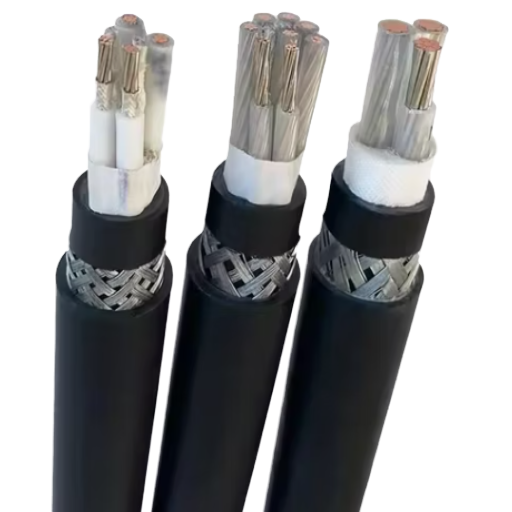
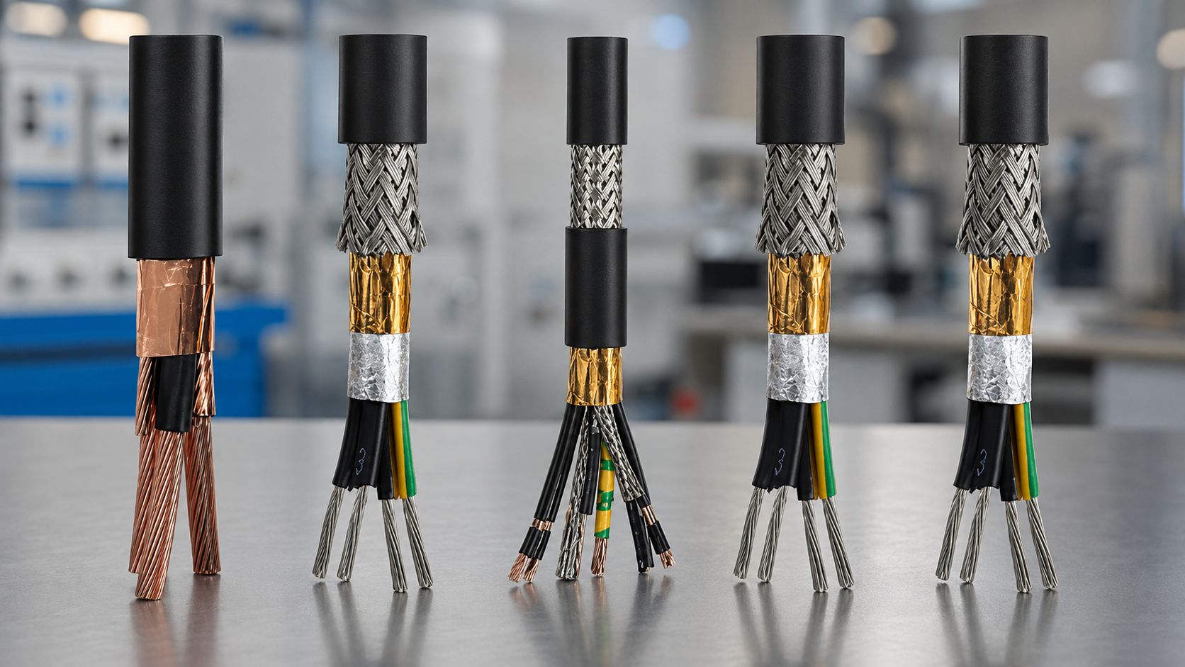
The four published screens differ from each other only in screen level:

BPKXGGP2 Single screen · copper braid
BPKXGGPP2 Double screen · braid + steel tape
BPKXGP2GP2 Double screen · tape + overall tape
BPKXGPP2GPP2 Double screen + double total screen

VFD Cable Fit for Drive-Output and Control Circuits

Longer cable runs increase reflected-wave stress at the motor because a pulse-width-modulated output behaves differently from a mains-frequency sine wave. The drive, cable and motor form one electrical system, so the final release check must cover more than conductor area.

Conditions changing the cable decision

Waveform

switching rise time and the motor insulation system set the reflected-wave question.

Route

total drive-to-motor length, parallel runs and separation from instrumentation affect electromagnetic interference exposure.

Ground path

shield termination, protective earth and enclosure bonding must be read as separate conductors with separate jobs.

Environment

stationary routing, repeated flex, oil, moisture, ultraviolet exposure and fire performance require their own written ratings.

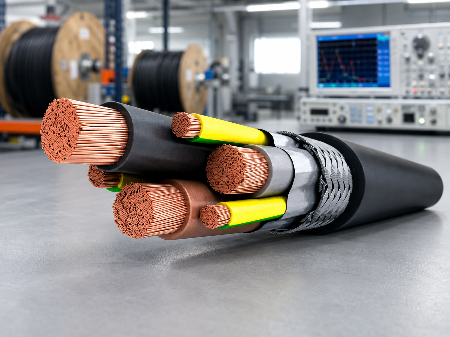
VFD Cable installation environment

VFD terminology and claim boundaries

Variable frequency drive cable Across VFD applications and wire and cable catalogs, this phrase identifies a circuit role; VFD systems still need a model-level record.
Switching stress High voltage spikes can appear at the motor on a variable-frequency drive output, but “high voltage” and “high-voltage cable” remain product-rating questions rather than claims for these models.
Insulation interface Cable insulation, voltage level, conductor size and drive electronics must be checked together for an AC motor; the Jinyou parameter table below does not turn those fields into ratings.
Noise control Braid shields and their terminations can help mitigate electromagnetic interference (EMI), but reducing electrical noise depends on the full grounding path and route.
Failure boundary & Environment A cable failure or motor failure cannot be attributed to the cable name alone. A VFD-specific selection has to name the environmental conditions the cable must survive; calling a route one of the industrial environments is not a rating, and written ratings are still required for the exact model.
Industrial cable terminology and specifications

Suitable starting point

the shielded control, signal and auxiliary circuits that run with a fixed drive-to-motor installation and match one of the four published shield builds.

Separate evidence required

voltage class, ampacity, bend radius, flex-life, flame rating and system EMC result.

Wrong choice risk

a cable that fits the terminals yet leaves the insulation or shield path unverified.

Decision rule

confirm against the drive manual, motor data, selected model record and local installation rules.

Model-Bound VFD Cable Construction and Parameters

Model matching requires the drive, cable and motor to be read together. The risk of mismatch or failure starts because a catalog label is treated as a complete specification, so the release record has to carry the Jinyou Cable model row plus the drive, motor and route facts the project produces itself. Independent PNNL guidance covers waveform, run length and grounding at system level, and the IEC 61800-3:2022 system scope reinforces why a cable entry cannot stand in for the whole circuit.

In 2026, a university study measured an 11 kW drive against 1 m, 3 m and 16 m motor feeder cables for terminal overvoltage, shaft voltage and bearing current. That is a motor-power result, not a control-cable one, and it is exactly why the feeder is specified separately from the four control-cable rows below—route length belongs in the release record for both.

VFD Cable Application

Jinyou frequency-conversion cable parameter set

Model or field Published value Shield level published Construction meaning
BPKXGGP2 1–20 cores · 0.75–2.5 mm² Single screen — copper braid Silicone rubber insulated, copper braid shielded, silicone rubber sheathed variable frequency drive control cable.
BPKXGGPP2 1–20 cores · 0.75–2.5 mm² Double screen — braid plus steel tape Silicone rubber insulated, copper wire braided, steel tape wrapped double shielded…
BPKXGP2GP2 1–20 cores · 0.75–2.5 mm² Double screen — copper tape + tape Silicone rubber insulated, copper tape shielded, copper tape overall shielded…
BPKXGPP2GPP2 1–20 cores · 0.75–2.5 mm² Double screen + double total screen Silicone rubber insulated, copper wire braided and copper tape wrapped double total shielded…
Core-count field 1–20 cores Not a model row Confirm the selected core arrangement against the drive, motor, brake, thermal-sensor.
Nominal area field 0.75–2.5 mm² (18 AWG to 14 AWG) Not a model row Use the model row as a construction boundary, not as a stand-alone ampacity result.
Temperature -60°C to 180°C Not a model row The published endpoints stay tied to this named frequency-conversion cable description.

How the four screens differ

The screen level is the only field that separates the four rows: everything else is published identically. Proper laying spacing with effective shield grounding reduces electrostatic coupling interference.

What it settles:

which of the four rows to shortlist when the route runs near analog, network or instrument wiring.

What it does not settle:

no transfer impedance, screening-attenuation figure, coverage percentage or EMC test result is published.

Fields to bind before release

  • Drive maker, drive model, output voltage, carrier settings and any output reactor or filter.
  • Motor voltage, insulation system, terminal layout, protective-earth point and encoder/brake.
  • Total installed length, tray or conduit route, grouping, ambient conditions and fixed-duty.
  • Required product marking, voltage rating, flame or oil rating, and destination-market acceptance.

“This cable is primarily used for controlling weak voltage and current signals in the control circuit of a variable frequency drive.”

— Jinyou Cable, frequency conversion cable product page

Shielding, Grounding and EMC Decision Rules

Bonding a screen at both ends can improve high-frequency noise rejection, but in a low-voltage signal circuit it can also create a ground loop, so the equipment instructions decide which rule applies. The Drive-Output Evidence Grid below keeps those two cases apart. Motor-power shields and signal shields therefore need separate rules, and the selected drive manual remains the controlling installation reference.

Drive-Output Evidence Grid

Decision point Cable construction to inspect Which published screen speaks to it Installation question Evidence to retain
High-frequency drive output Insulation system, shield coverage and ground conductors None — the source page publishes no voltage class, insulation thickness or withstand figure for any of the four What are the output rise time, run length and motor withstand limits? Drive manual, motor record and cable test sheet
Noise near analog or network wiring Copper braid, copper tape or combined shield path All four, and this is the only row where the published screen level separates them: BPKXGGP2 single, BPKXGGPP2 and BPKXGP2GP2 double, BPKXGPP2GPP2 double plus a total screen Is shield continuity preserved through glands, junctions and enclosures? Route drawing and termination detail
Bearing-current concern Grounding symmetry and low-impedance return path None — no symmetrical-ground or 3+3 conductor arrangement is published for these models How are protective earth, shield and motor frame bonded? Grounding diagram and commissioning readings
Long drive-to-motor route Voltage rating, insulation, capacitance and shield None — route length is a system result and no capacitance or length limit is published for these models Does the drive maker require a reactor, filter or shorter route? Approved system calculation and maker limit
The IEC 61800-3:2022 scope applies to the power-drive system and machine tool, not just the cable. A 2026 Ghent University study measured cable type, cable length and motor grounding as distinct variables in a pulse-width-modulated drive system.

Not Always Transferable

A one-end signal-shield rule cannot be copied to a VFD motor-power shield.

Not Interchangeable

A protective-earth conductor is not the same thing as a high-frequency shield termination.

Common Assumption

A braided shield label alone proves nothing about gland contact or shield continuity through a junction.

Counter-Intuitive Result

The weakest unshielded transition can dominate an otherwise shielded route.

Failure Points Transition

A screen is only as good as its least continuous point, which is why every row above ends in an installation question rather than a construction. Four transitions decide it, and none of them is a property of the cable.

None of the four Jinyou rows changes any of these four answers. The screen level narrows which construction to shortlist; the terminations decide whether the shortlisted construction performs as specified once installed.

Gland and enclosure entry.

A screen landed through a full circumferential gland keeps its high-frequency path; a screen gathered into a pigtail tail turns that path into an inductor at exactly the frequencies the drive produces. Record which one the installation uses at each entry.

Junctions and pull boxes.

Every junction is a chance for the screen to stop. A cable specified with a double total screen and interrupted at one junction box performs like the unshielded section, not like the specification.

Separation from what it must not couple into.

The OSHA electrical definitions treat raceway, conduit and enclosure as parts of the wiring method, not as accessories: grouping and separation belong in the route drawing beside the cable model.

Where the screen lands, and at how many ends.

The one-end rule used to stop ground loops on a low-level signal pair is not the motor-power rule; PNNL variable-speed-drive guidance treats grounding, filtering and run length as functional installation variables.

Documentation & Evidence Control

  • Record common-mode current and radio-frequency interference observations separately from the cable model name.
  • Ask whether the construction uses foil, copper braid or a combined screen; do not transfer a screen description from another family.
  • Compare symmetrical ground and 3+3 grounding only when the selected cable record defines those conductors.
  • Keep XLPE insulation, jacket, conductor cross-section, conduit separation and motor bearings as explicit review fields, not assumed Jinyou ratings.
  • Action Required: Shield-Continuity Check Run the shield-continuity check to organize the evidence for one circuit. It records questions and boundaries; it does not certify an installation.

Selecting Cores, Cross-Section and Temperature by Model

Ampacity alone does not select a VFD cable; voltage, conductor temperature, grouping, route and output waveform stay in the same review. The OSHA ampacity definition ties continuous current to the conditions of use and the conductor temperature rating.

How to read the published size band

Start with the drive and motor interface, then map every required phase, protective-earth, sensor, brake and signal conductor.

Check the selected model construction before applying the 1–20 core range; the table does not define every possible internal arrangement.

Treat 0.75–2.5 mm² as the nominal cross-sectional band published for the family, not as a VFD cable ampacity chart. The AWG equivalent is roughly 18 AWG to 14 AWG; that is a unit conversion for readers who specify in AWG, not a published Jinyou marking.

Bind -60°C to 180°C to the source-family wording and verify the marking, installation temperature and moving-duty condition for the selected model. This is the widest field the source page publishes, and it is the one figure that can be decisive on its own: a hot drive cabinet, a furnace or kiln auxiliary, a steel-mill or foundry route, or an outdoor circuit that sees deep cold will disqualify a cable on temperature before any screen question is reached. The endpoints stay tied to the published family description; no thermal endurance or service-life result is published for them.

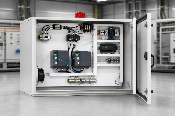
Industrial VFD Drive Cabinet and Interface

VFD cable sizing release matrix

Input Acceptable evidence Release blocker
Conductor count Drive/motor wiring diagram aligned to the selected model An assumed spare core or unlisted mixed function
Conductor area Current calculation with temperature, grouping and route conditions Copying a VFD cable size chart without its assumptions
Voltage stress Drive and motor instructions plus cable voltage marking Treating cross-section as proof of voltage rating
Mechanical duty Written fixed-installation or moving-duty limit Calling flexible VFD cable drag-chain cable without a flex-life record
Environment Written oil, wet, UV, flame and temperature ratings as required Transferring a rating from another Jinyou cable family

Run the model-bound selector to test a conductor count and cross-section against the published 1–20 core and 0.75–2.5 mm² band and read back the screen level that matches. It answers “no” when the requested arrangement falls outside what the source page publishes, which is a release blocker worth finding early; it is a shortlist for record review, not an ampacity calculation.

Jinyou Cable Manufacturing Context

Shanghai Jinyou Jinhong Intelligent Electric Co.,Ltd operates from Shanghai, and Jinyou Cable was established in 2006. The company brief covers cable design, manufacturing, custom OEM work and integrated electrical systems for solar power, energy storage and electric vehicles.

Factory Image 1
Factory Image 2
Factory Image 3
Factory Image 4
Factory Image 5

Production Line Evidence

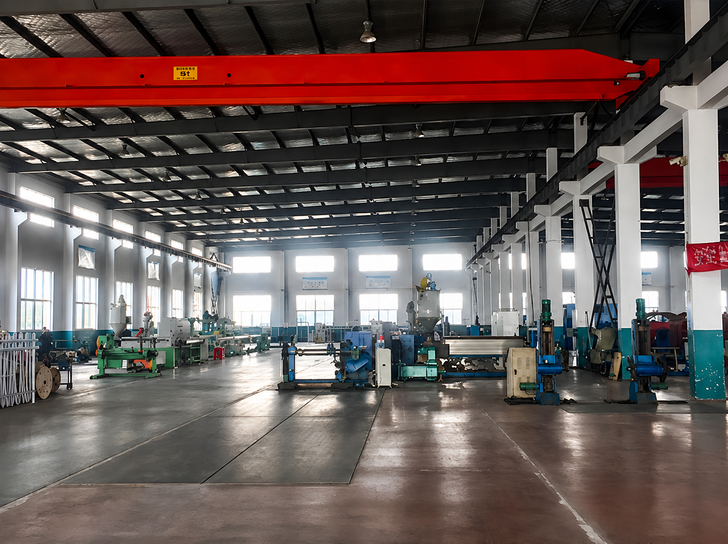
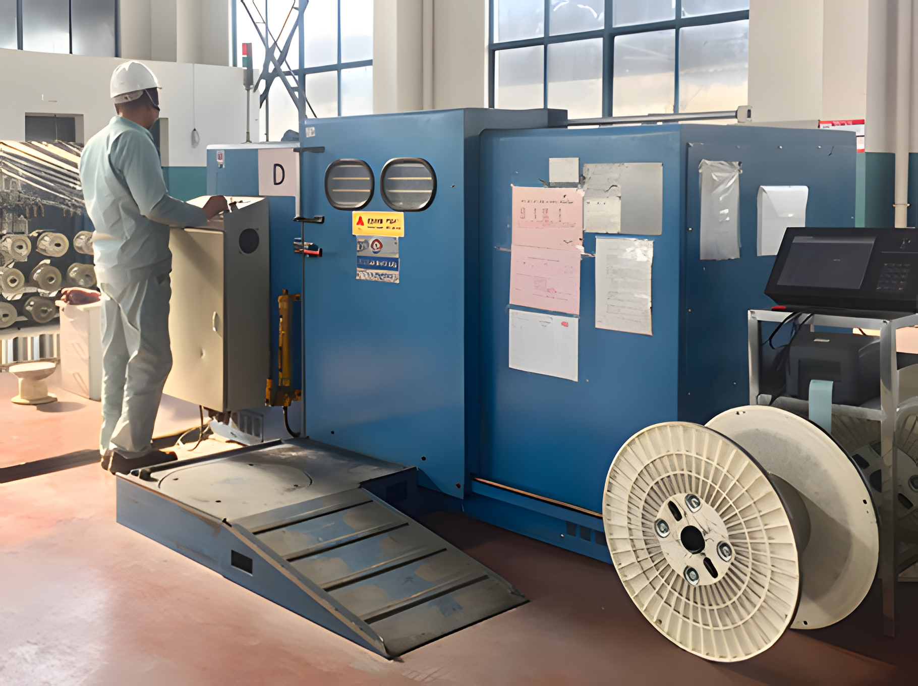
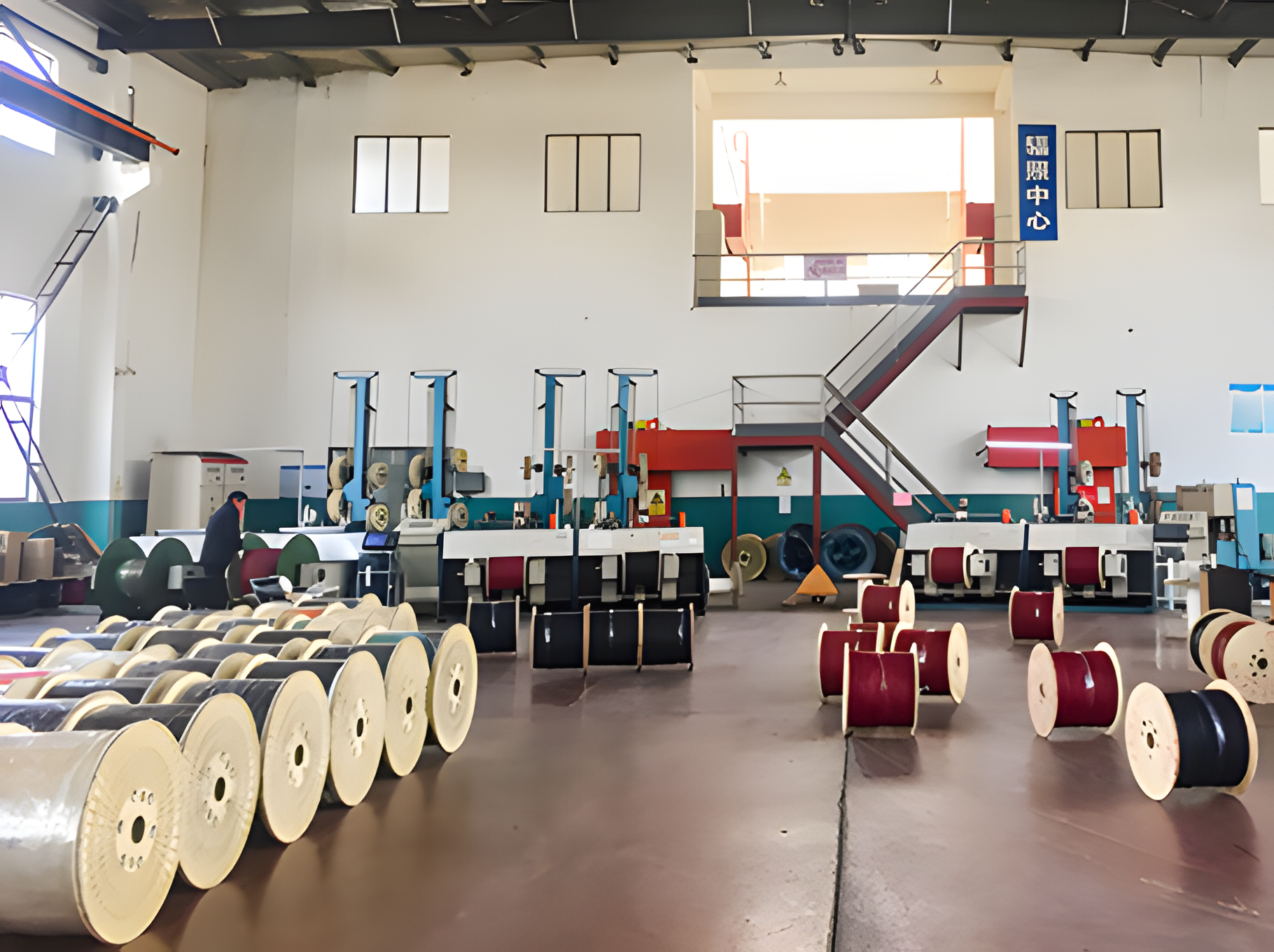
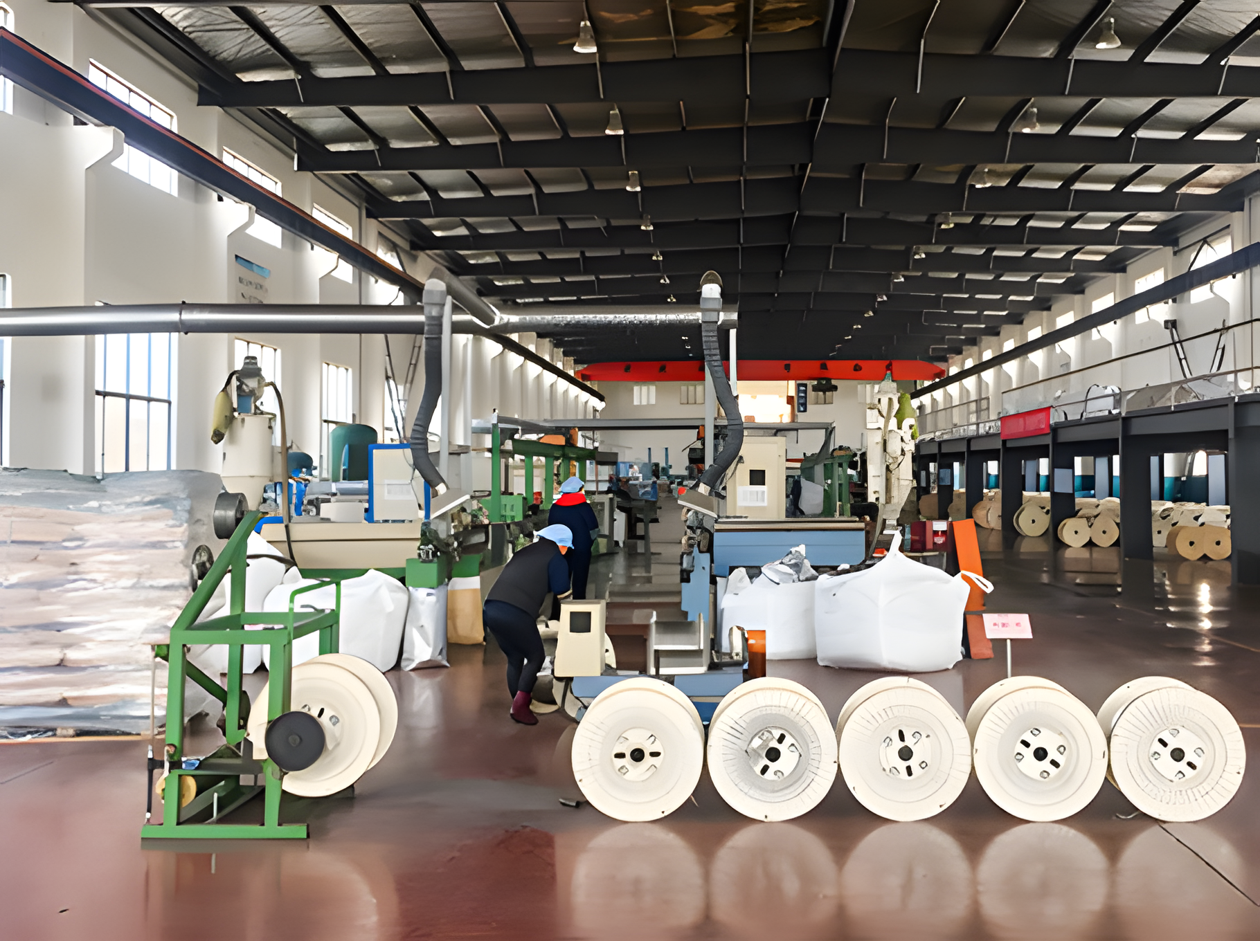
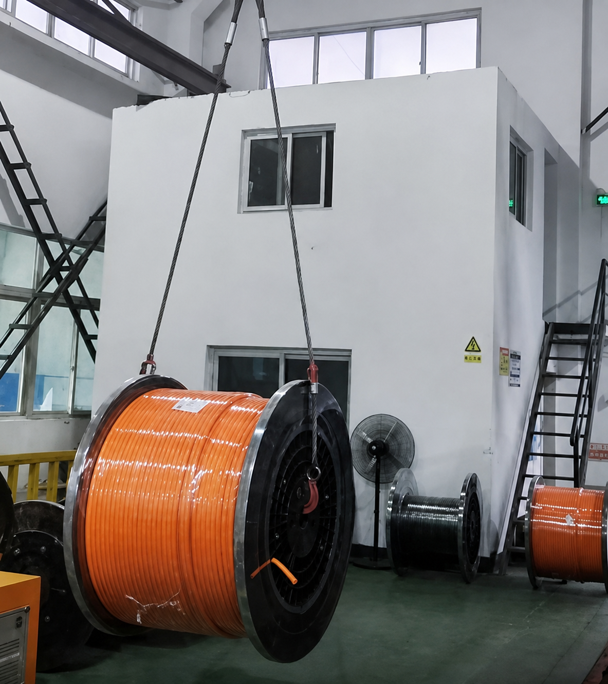
Extrusion and stranding lines with loaded take-up reels, from Jinyou Cable’s public factory photo page. The image supports manufacturing context only; it shows no VFD-specific process step.

Manufacturing Base

Shanghai facility with automated machinery and testing systems.

Business Model

Standard cable supply and custom OEM development for defined installation needs.

Export Scope

Project support for international markets with destination-specific requirements.

Published Approvals

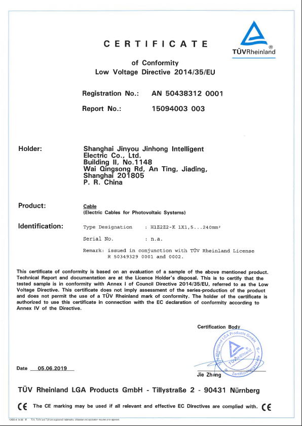
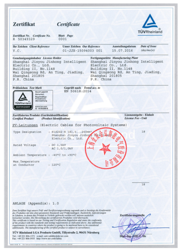
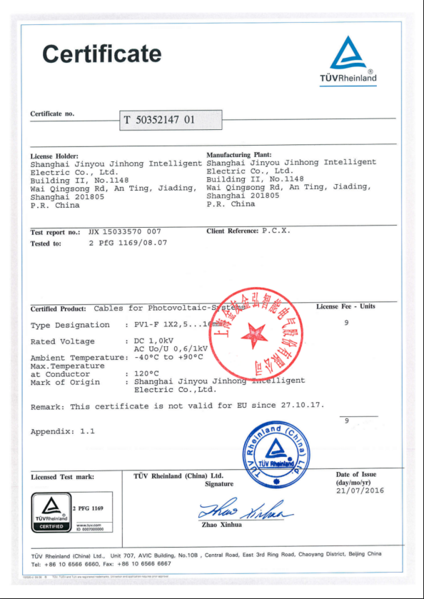
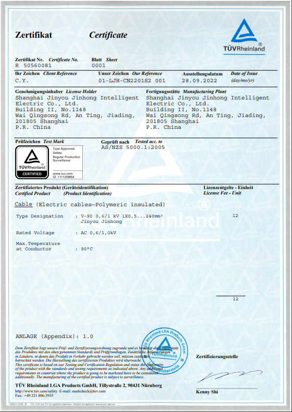
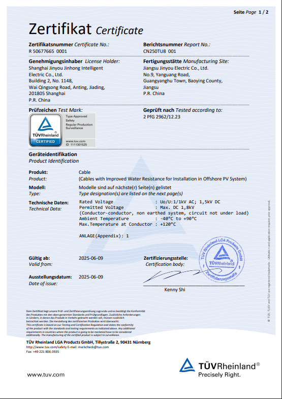
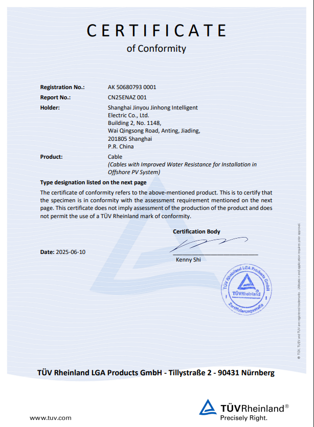
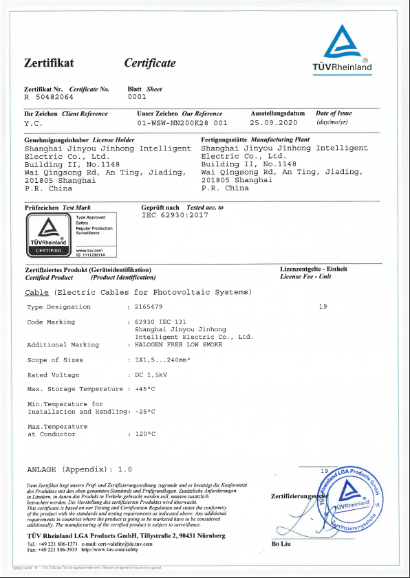
The public certificate display page is where a buyer checks what carries an approval today; the records shown there are issued for other cable families, so no published approval on that page covers a VFD model—ask the supplier which certificate, if any, exists for the selected construction.

Evidence Boundary

The factory image supports manufacturing context; the selected model record controls VFD cable ratings.
Source-Bound Quality and Inspection Plan

Jinyou Cable operates automated machinery and testing systems in its Shanghai manufacturing facility. The acceptance plan for a VFD cable order should still name the selected model, test method, sample count, unit and pass/fail limit in writing.

1

Freeze the construction.

Put the exact model name, conductor schedule, shield build, sheath and marking text on the controlled order record.

2

Set incoming controls.

Link conductor, insulation, tape, braid and sheath materials to the approved bill of materials.

3

Check the build.

Record the in-process dimensions and shield or tape work named in the inspection plan.

4

Verify finished cable.

Apply the written electrical, dimensional, marking and packing checks for the selected model.

5

Release against one record.

Keep the result, units, test date and disposition beside the shipment identity.

VFD Cable Quality 1
VFD Cable Quality 2
VFD Cable Quality 3
VFD Cable Quality 4
VFD Cable Quality 5
VFD Cable Quality 6
VFD Cable Quality 7

Evidence that belongs with the cable decision

  • Product drawing and conductor schedule for the selected Jinyou model — the published starting point is the frequency conversion cable parameter page, which carries the four model rows and nothing beyond them.
  • Record the voltage, temperature, flex, environmental and flame ratings specified by the receiving project.
  • Shield construction and termination details matching the installed glands and enclosures.
  • Test-report scope tied to the exact construction rather than an alternate cable model. Jinyou keeps a public test report library, and the files released there belong to other cable families.
× Enlarged Image

Pricing and Delivery Inputs

VFD cable price follows the selected model, conductor build, total length, reel plan, test scope, packaging and destination requirements. A fixed public price would hide the same variables that decide technical fit. A price or delivery surprise after the drive and motor are fixed usually means one of those inputs moved — the conductor schedule, the reel plan or the test scope — and that is the reason they are frozen onto the order record before a model is released.

Inputs that move price and delivery

Input
Why it changes the work
Decision record
Model and shield build
Braid, steel tape, copper tape and combined builds use different materials and process steps.
Exact Jinyou model string
Core count and area
Conductor count and 0.75–2.5 mm² selection change copper content and cable geometry.
Approved conductor schedule
Order length and reel split
Continuous lengths, cut lengths and reel limits change production and packing work.
Length list by reel
Test and marking scope
Destination rules and project acceptance determine the records and markings required.
Inspection and marking schedule
Packaging and route
Reel protection, moisture barrier and transport handling follow the shipment plan.
Packing specification

System value without an invented payback figure

Correct model selection reduces the chance of an expensive redesign after the drive and motor are fixed.

A complete shield path cuts troubleshooting ambiguity when nearby signal circuits show noise.

Written voltage, temperature and route assumptions keep the purchase record aligned with the installed circuit.

The trade-off is clear: a cheaper catalog line costs you more if missing evidence forces a new cable or filter decision.

Stop-and-Reselect Conditions

Applications Mandating a Specialized Cable Infrastructure

The four standard VFD constructions are fundamentally inadequate for environments subjected to extraordinary thermal, mechanical, or dielectric stresses. When the operational duty cycle breaches standard application profiles, mitigating catastrophic failure requires transitioning immediately to a purpose-engineered cable basis.

Continuous High-Speed Drag-Chain Motion

Why standard VFD cables fail here A jacket’s tactile softness does not equate to dynamic repeated-flex cycle endurance, minimum bend radius tolerances, or torsional resistance. Standard PVC or PUR control cables installed in C-tracks inevitably suffer from core friction, “corkscrewing,” and rapid copper fatigue under high-speed acceleration.
The required engineering basis Transition immediately to Jinyou’s specialized robotic servo and drag-chain cable family. These constructions are engineered with exceedingly fine wire stranding and specialized slip agents. The technical data sheet must explicitly publish tensile load limits, severe abrasion resistance, tear propagation metrics, and halogen-free cross-linked parameters. Cycle life is heavily dependent on track radius and travel velocity; hence, empirical testing data is mandatory prior to specification.
High speed robotic drag chain system in automated manufacturing facility

Medium-Voltage (MV) Drive Output Stress

Why standard VFD cables fail here Standard LV VFD cables provide no verified voltage class for medium voltage (e.g., 1.8/3kV or higher), insufficient insulation radial thickness, and zero partial-discharge corona mitigation. Furthermore, they do not align with the strict IEC 61800-5-1 safety protocols governing MV drive systems and clearance requirements.
The required engineering basis Specification must shift to dedicated MV variable frequency cables constructed with semi-conductive screens over both the conductor and insulation to manage severe electrical stress and prevent corona discharge. Rely strictly on the project’s absolute voltage standard, peak inverse voltage (PIV) ratings, and a certified factory acceptance test (FAT) record for partial discharge.
Medium voltage electrical switchgear and industrial drive cabinet

Hazardous, Explosive, & Classified Locations

Why standard VFD cables fail here A generic VFD cable possesses no intrinsic safety (IS) ratings. Circuits traversing explosive atmospheres demand rigid location, gland compatibility, and specific installation approvals. Machinery wiring rules—such as ATEX directives, IECEx standards, or NFPA 79:2024—apply strictly to the complete installation method, not merely the cable’s generic marketing name.
The required engineering basis Utilize the exact destination code, equipment classification (Class, Division, Zone), and approved wiring methods (e.g., steel wire armor, specialized mud-resistant jackets). For petrochemical or mining applications, the cable must bear verifiable third-party certification ensuring absolute containment and zero spark propagation during catastrophic faults.
Hazardous industrial petrochemical environment requiring ATEX certified cabling

Aggressive Oil, Wet, Sunlight, or Flame Exposure

Why standard VFD cables fail here The source page may claim general “weather resistance” or “oil tolerance,” but subjective marketing vocabulary is legally and technically meaningless. Unrated jackets suffer extreme swelling, embrittlement, or catastrophic jacket failure when exposed to harsh industrial cutting fluids, prolonged UV radiation, or direct flame.
The required engineering basis Isolate every specific environmental exposure and demand the corresponding normative marking (e.g., UL Oil Res I/II, direct burial rating, UV resistance per ISO 4892, or flame retardance per IEC 60332-3). Advanced thermoset compounds like CPE or highly alloyed polyurethanes are often necessary to maintain sheath integrity over a 20-year operational lifecycle.
Sparks and flame exposure in heavy industrial metallurgical facility

High-DC Electric-Vehicle or PV Solar Circuits

Why standard VFD cables fail here AC drive-to-motor duty and DC EV/PV cable applications operate on fundamentally different physics and thermal profiles. Standard AC VFD cables lack the stringent DC voltage endurance, extreme temperature ratings (often 120°C for PV), and severe weatherability required for solar arrays or high-amperage liquid-cooled DC fast chargers.
The required engineering basis Select exclusively from the exact Electric Vehicle or Photovoltaic families within Jinyou’s catalog. PV cables must meet EN 50618 (H1Z2Z2-K) standards for double-insulated, ozone-resistant performance. A VFD control-cable row is structurally incompatible and legally non-compliant as a substitute for these specialized high-DC applications.
Commercial solar photovoltaic panels and high DC voltage infrastructure

Heavy Motor Power Feeder (Drive to Motor)

Why standard VFD cables fail here The four standard constructions detailed are fundamentally control cables, optimized for signal and auxiliary circuits. The general source page provides no heavy-duty voltage class (e.g., 0.6/1kV) and zero certified ampacity ratings necessary to safely sustain continuous high-amperage motor power delivery without catastrophic thermal runaway.
The required engineering basis Specify a dedicated motor supply cable rated for the drive’s output voltage and continuous load current. Jinyou publishes a distinct cross-linked polyethylene (XLPE) power cable family rated 0.6/1 kV (max system 1.2 kV), featuring a 90°C continuous conductor temperature and a 250°C short-circuit limit (5 seconds), available in heavily armored 3+2 and 4+1 configurations. Note: As this is not inherently a symmetrical-ground VFD construction, EMC shielding parameters must be addressed separately.
Heavy XLPE insulated industrial motor power feeder cabling

Motor Lead-Out & Internal Winding Connection

Why standard VFD cables fail here The external VFD control-cable record does not address the extreme conditions found inside the motor housing. Lead-out wiring must withstand direct contact with hot copper windings, baking varnishes, and intense rotational vibration—environments that rapidly degrade standard PVC or XLPE insulation.
The required engineering basis Transition immediately to a specialized motor lead wire family (e.g., silicone or fluoropolymer insulated). These wires must be explicitly certified for Class F (155°C) or Class H (180°C) thermal thresholds and demonstrate chemical compatibility with epoxy resins and impregnating varnishes to prevent dielectric breakdown within the stator.
Exposed copper motor windings and high temperature lead out wiring

Long Route dV/dt & Reflected Wave Overvoltage

Why standard VFD cables fail here In extended cable runs (typically exceeding 30-50 meters), the rapid switching frequencies of modern IGBT inverters create severe standing waves. A cable shield alone cannot absorb the sheer magnitude of these reflected wave spikes, which can double the terminal voltage, violently exceeding the motor’s corona inception voltage (CIV) and destroying stator insulation.
The required engineering basis The problem transcends the cable alone; it requires a holistic drive-cable-motor system analysis. Depending on the exact cable capacitance, inductance, and route length, mitigating this phenomena dictates the precise specification of line reactors, dV/dt filters, or sinusoidal filters at the inverter output. Merely increasing conductor cross-section is technologically futile.
Long factory production line demonstrating extended cable routes

Systematic Integration Note: A review of recent reflected-wave suppressor patents vividly illustrates why impedance matching and filter selection inherently belong to the integrated drive–cable–motor architecture rather than isolated component selection. Up-sizing the conductor is rarely the remedy for complex electromagnetic phenomena. True reliability is achieved solely through rigorous, condition-specific engineering.

VFD Cable Technical Utility Suite

VFD Cable Model Selector

Enter any core count and nominal area. The tool answers no, with the reason, when the request falls outside the published 1–20 core and 0.75–2.5 mm² band — try 24 cores or 6 mm² to see it. Inside the band, all four constructions share the same figures, so the screen build is the only field that separates them.

Access Selector

VFD Shield-Continuity Check

Separate motor-power shielding from signal-shield decisions and record the continuity check. This ensures optimal electromagnetic compatibility (EMC) and mitigates high-frequency noise typical in variable frequency drive systems. Evaluate shielding effectiveness across the entire cable run to guarantee reliable motor performance.

Run Continuity Check

VFD Cable Evidence Checklist

Tick what is already recorded. The list prints what is still missing before release first, with the records already on file underneath. This streamlined validation process ensures compliance with critical industry standards prior to installation, maintaining complete traceability of all necessary test protocols and certifications.

View Checklist
Knowledge Base

VFD Cable Selection FAQs

What is a VFD cable?

A VFD cable carries power or control functions between a variable frequency drive and its motor-side equipment under a switched output waveform. The useful definition comes from the exact construction, voltage and temperature marking, grounding path, route and equipment instructions—not the name alone.

Are VFD cable and inverter cable the same?

The terms overlap in drive-to-motor work, and Jinyou’s table uses both “variable frequency drive control cable” and “inverter control cable” in its construction names. Compare the full model record before treating two names as equal.

Does every VFD cable need a shield?

Shield need and form come from the equipment instructions, the electromagnetic environment and the installation rules. A shield also needs a continuous, low-impedance termination path; a shield label without that path does not settle the EMC question.

How is VFD cable shield grounding handled?

Separate the motor-power shield, protective earth and signal shields in the drawing, which is the split the Drive-Output Evidence Grid is built around. Follow the drive and motor instructions for bond points, gland contact and continuity, because the one-end rule used for some signal circuits is not a universal motor-power rule.

What belongs in a VFD cable specification?

State the drive and motor models, output voltage and settings, total route length, conductor schedule, cable model, voltage and temperature ratings, shield build, grounding method, fixed or moving duty, environmental ratings, markings and acceptance tests.

How should VFD cable sizing be checked?

Start with load current and equipment instructions, then apply conductor-temperature, grouping, route and ambient conditions. Check voltage drop and motor-side waveform limits separately; 0.75–2.5 mm² is a product-family band, not a completed sizing result.

Can the Jinyou size band be used as a VFD cable ampacity chart?

No. The public table gives nominal cross-sectional area, while ampacity is tied to the conditions of use and the conductor temperature rating.

When do reflected waves enter the decision?

Reflected-wave review becomes relevant when fast drive-output edges, cable length and the motor’s impedance or insulation system combine to raise motor-terminal stress. Use the drive maker’s limits and a system study rather than a universal length cutoff.

What does UL Subject 2277 cover?

UL Solutions lists UL Subject 2277, sixth edition dated 2024-12-02, for the Flexible Motor Supply Cable category. A project still needs the selected cable’s own listing or marking record before that category can be claimed for a product.

Which four Jinyou models appear in the public parameter table?

BPKXGGP2, BPKXGGPP2, BPKXGP2GP2 and BPKXGPP2GPP2. Each row carries a distinct braid, steel-tape or copper-tape shield description.

Is flexible VFD cable automatically suitable for a drag chain?

No. Softness and elasticity are not a flex-life record; repeated-motion duty needs cycle, speed, acceleration, bend radius and installation data for the exact model.

What drives VFD cable price?

Model construction, conductor count and area, total length, reel plan, test scope, marking, packaging and destination requirements move the cost. Fix those inputs before comparing figures.