Get in touch with JINYOU Cable Company

Quick Specs: The Calculation Used in This Guide
These are hypothetical teaching inputs, not a cable specification or installation approval.
| Circuit | Two-wire DC loop; equal outgoing and return lengths |
|---|---|
| Assumed operating point | 600 V DC at the source; 15 A |
| Assumed loop resistance | 0.32 Ω, held constant for the example |
| Calculated cable-only result | 4.8 V drop; 72 W of conductor heat |
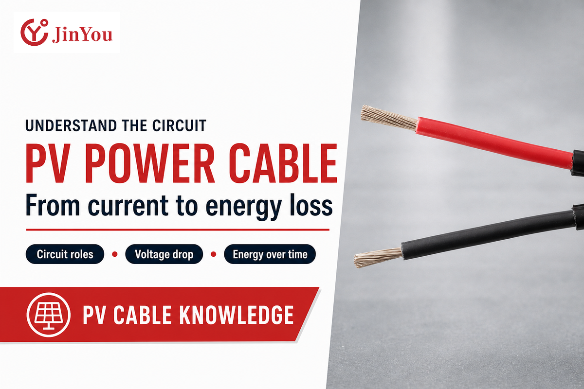
A cable can transport current without delivering all of the source power to the inverter. This distinction is often lost during discussions that start with “4 mm² or 6 mm²?” The PV Power Cable guide starts with a circuit, considers voltage and resistance, and includes the importance of time to show what loss calculations truly do. This guide integrates solar energy theory with the questions raised when comparing electrical cables for an actual project.
PV power cable carries electrical power in a photovoltaic system. On a DC circuit, voltage drop is equal to current times loop resistance. Selection of cable also has to take into account temperature, installation and connection considerations.
Key Points
- A low voltage-drop result doesn’t establish safe current capacity.
- At fixed resistance, doubling current quadruples conductor heating.
- Average current can understate energy loss across changing operating periods.
- In a solar PV system, sunlight resistance, suitability for wet locations and permission to be buried in the ground are three different properties.
Where PV power cable fits in the DC circuit
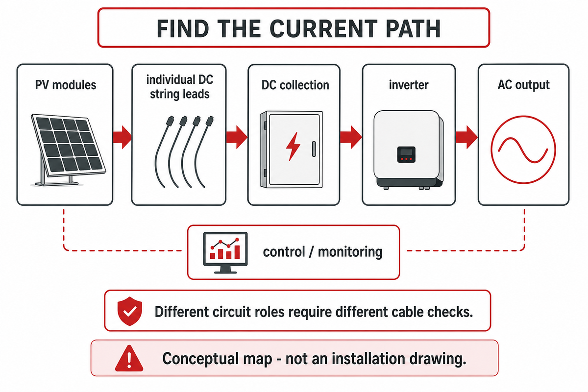
PV power cables connect power-producing devices to power-converting devices in a photovoltaic system. On the array side, cables transport current that flows from each individual module to form a string, and combined strings can form a circuit that carries current to an inverter. The environment surrounding the cable determines the stress conditions that it must withstand.
The term “solar cable” often covers multiple products in day-to-day conversations. Solar wire and cable serve power distribution and connections immediately behind a module. A module lead, a combined DC feeder and an AC export connection serve a solar power system, but they don’t serve the same application. Key differences concern circuit conditions of duty and installation. Control and monitoring conductors have different duties again. A ground wire for solar panels serves a protective function and must not be treated as a normal power circuit conductor. Solar installers must make these distinctions when assessing residential and commercial drawings. This manual considers cable used for direct current power delivery; it doesn’t regard every solar system cable as interchangeable. The requirements of solar power systems must be assessed against the actual circuit.
What type of wire is used for PV?
PV circuits use various types of wire and cable that are constructed and marked in accordance with the particular circuit and destination. Exposed module wiring, protected feeders and inverter output circuits can have different requirements. Begin with the electrical drawings and equipment instructions and identify the products and installation requirements of the cable before comparing conductor sizes.
This distinction is important when connecting solar panels to inverters or a charge controller. In a solar installation, the intended use must be clear before a product comparison is made. An insulation voltage marking is a product limitation, not a determination of the voltage that a given array will generate. Likewise, “solar photovoltaic” in a product description doesn’t grant all permissions for an installation.
Circuit takeaway: Locate the current path before calculating cable performance. The University of Maryland separates PV source circuits from combined output circuits; a 15 A string and a feeder collecting multiple strings need different current inputs. Often times, a useful cable calculation follows the actual drawing, not the product category name. University of Maryland wiring and fusing guidance.
Solar panel strings: what series and parallel change
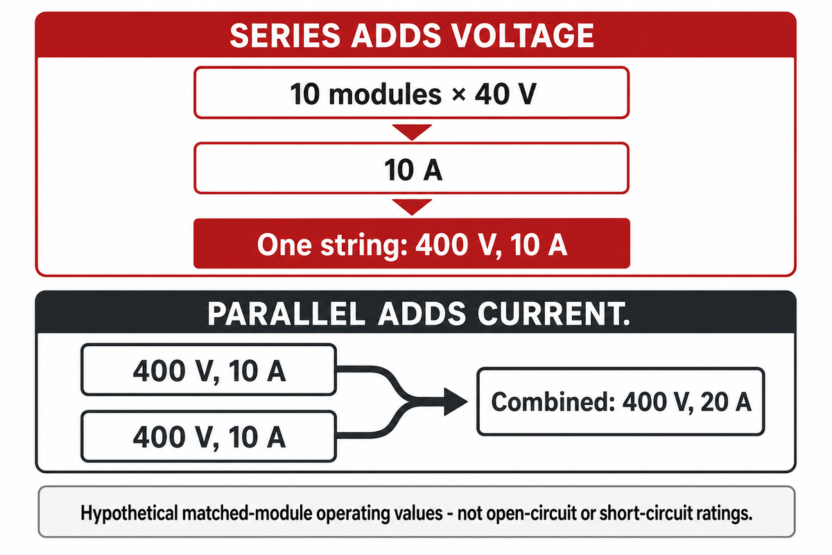
Wiring solar panels in series or parallel changes the electrical quantities that a cable sees. When similarly operating modules are series connected, the module string voltage is the sum of the module voltages and the string current is approximately the same as the module current. Parallel strings connect at a common point and add string currents to that point. Because of these relationships, the position of a string relative to the point of collection affects the current carried by a cable.
One example shows 10 identical modules operating at 40 V and 10 A. One series string has a nominal example operating point of 400 V and 10 A. Two such strings in parallel would give a combined voltage of approximately 400 V and a current of 20 A at the common point. Each string lead still carries its own current; the combined conductor carries their sum.
These are operating values, not open-circuit or short-circuit values. Output of solar panels must be explained for the operating condition that is being described. Real design of a system must involve module data, temperature, inverter limits, and the method of calculation. Mismatched modules, uneven irradiance and maximum-power-point tracking can move the operating point away from the simple example.
For engineers comparing the two layouts, the important question is: where do the currents merge? Shifting that reference causes a different cable segment to carry the larger current. A longer combined segment can dissipate more heat, even if the individual string leads remain the same. Depict the segments separately to show their individual losses. This keeps solar panel cables attached to their own current assumptions, which can change with layout.
Connection takeaway: In the hypothetical 400 V example, combining two 10 A strings produces a 20 A output circuit. Calculate each segment at its own current. Unequal wiring between parallel strings can also create mismatch, which is a separate effect from conductor heat. Sandia’s DC wiring loss model explains that distinction.
What cable markings and construction actually tell you
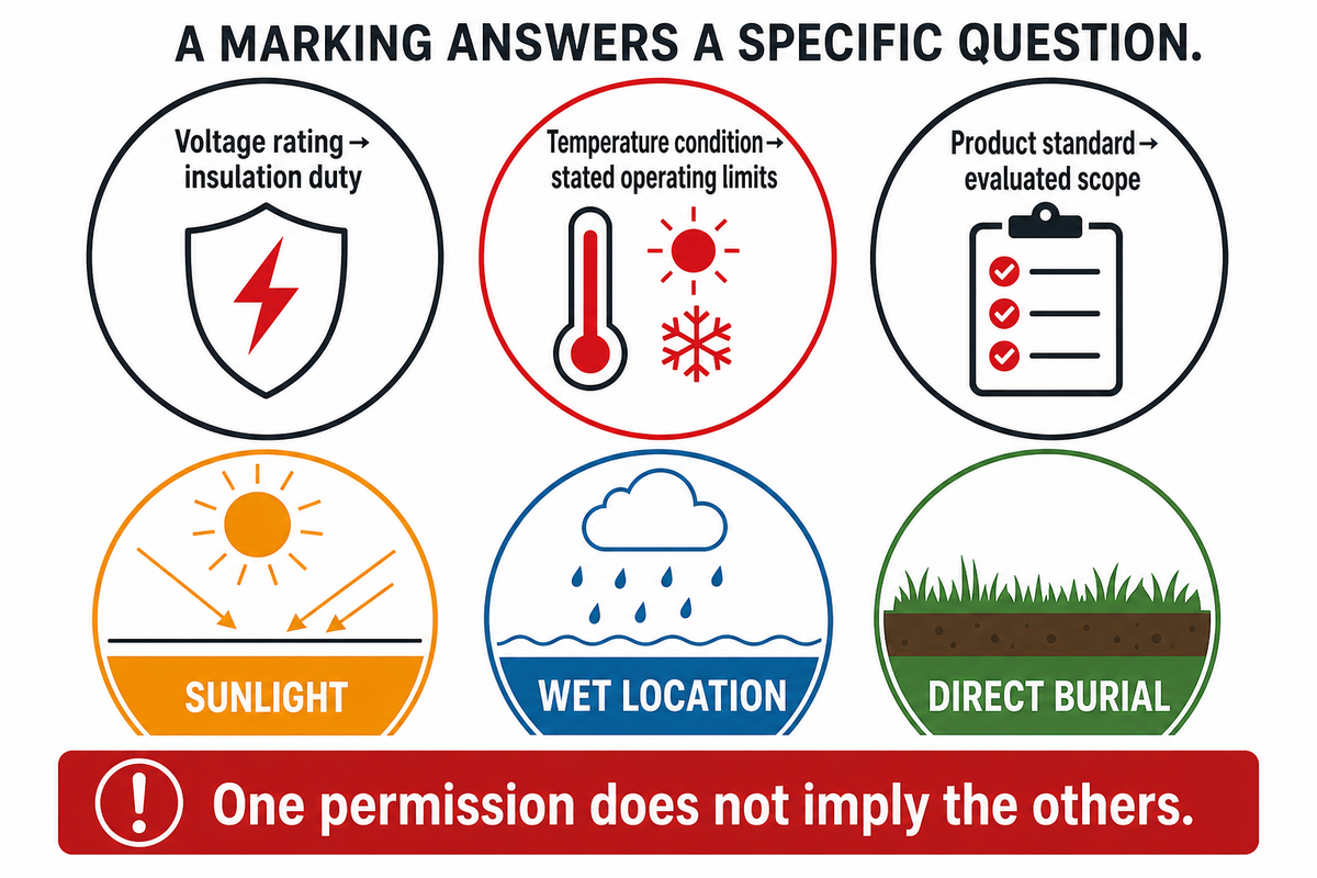
Cable markings depict a defined construction and tested or listed uses. They can denote size, voltage rating, temperature condition and product standard of a conductor. A description such as “2kV PV wire” communicates a voltage rating, not an expected array operating voltage. Cable markings do not necessarily provide authorization for all routes. A PV cable vs building-wire comparison should start with these conditions, rather than a shared nominal size. Read the complete marking alongside the exact product documentation, especially when moving between different solar markets or installation methods.
“Different global regulatory requirements specify which cables are appropriate to use.”
Insulation insulates conductive parts; the outer sheath faces environmental and use conditions. Cross-linked materials, low smoke properties and UV stability describe other attributes. The finished cable’s specified end use should be verified. Durability in outdoor environments depends on environmental exposure, not the word “outdoor” alone. “high-quality solar pv” is a marketing term and should not be assumed to mean the product is built to the specified requirements.
The public scope of IEC 62930:2017 covers single-core PV cables rated at 1.5 kV DC and distinguishes normal continuous operation at 90°C from operation at 120°C for 20,000 hours. Those conditions are not permission to operate every solar cable continuously at 120°C. EN 50618 and UL 4703 belong to different product-standard routes; the destination market and exact documentation matter.
What is the difference between PV wire and THHN wire?
PV wire and THHN wire are distinguished by their rated and permitted uses not simply by copper size or insulation color. A building wire may have additional markings to indicate that the wire is suitable for use in wet locations or for exposure to sunlight. Those markings must be evaluated individually; they do not establish equivalency with exposed photovoltaic wire.
For instance, in the case of Southwire’s SPEC10000, THHN is listed for dry locations up to 90°C and THWN-2 is listed for wet and dry locations up to 90°C, with separate oil-exposure conditions. The same specification uses a 600V rating and lists 8 AWG and larger as sunlight resistant. These are that manufacturer’s product conditions, not universal conditions for all regular cables.
Copper conductors can be bare or tinned. To compare copper wire, keep the material and plating description separate from the resistance value. The fact that tin enhances corrosion resistance should not be interpreted to mean that the plating increases copper conductivity. For any copper or aluminum, the conductor should be evaluated together with conductor material, termination suitability and resistance data. A comparable aluminum PV wire should be evaluated as a defined product, and not as a material only substitution.
How current and cable resistance create voltage drop
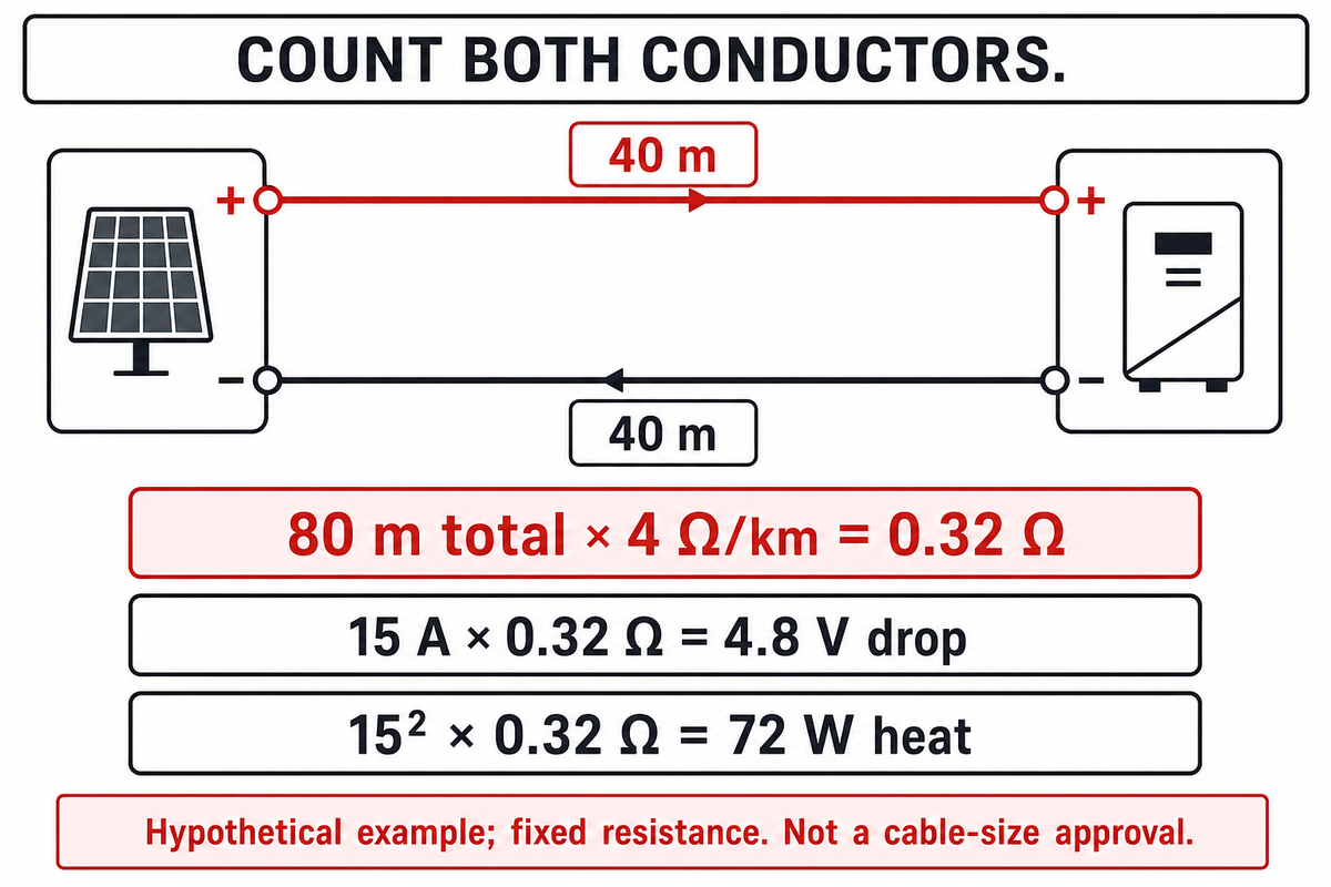
DC voltage drop is the operating current multiplied by the total series resistance of the current path. In a two-wire circuit, the resistance of both the outgoing and the return wire should be considered. Thus, for a one-way route, the length of the wire should not be considered the full conductor length, unless the return path is already accounted for in the calculation.
The basic relationships are ΔV = I × Rloop and Ploss = I² × Rloop. Sandia uses these for DC wiring. Victron’s Wiring Unlimited theory chapter also describes the effects of resistance in leads and connections. The examples with battery circuits describe the principle of circuits and are not solar cable ampacity recommendations.
The following calculation assumes a resistance value per kilometer. This is not a selected product’s value from its datasheet. A project calculation needs resistance appropriate to its operating temperature and conductor construction. Efficient power delivery is a design objective; a voltage-drop result is evidence for only part of that objective.
| Quantity | Example value | Meaning |
|---|---|---|
| One-way route | 40 m | Distance from source to receiving equipment |
| Total conductor length | 80 m | Two equal 40 m leads |
| Assumed conductor resistance | 4 Ω/km | Fixed for this teaching example |
| Loop resistance | 0.32 Ω | 4 × 80 ÷ 1,000 |
| Operating current | 15 A | Assumed current through both leads |
| Source operating voltage | 600 V DC | Not the insulation rating or open-circuit voltage |
| Cable voltage drop | 4.8 V | 15 × 0.32 |
| Drop relative to source | 0.8% | 4.8 ÷ 600 × 100 |
| Receiving voltage | 595.2 V | 600 − 4.8 |
| Conductor heat | 72 W | 15² × 0.32 |
Suppose PV extension cables add 10 m to the one-way route, keeping the same assumed conductor and current. Total conductor length becomes 100 m, loop resistance becomes 0.40 Ω, and the voltage drop becomes 6.0 V. Cable heating becomes 90 W. This hypothetical extension adds 18 W of conductor loss at that operating point; it does not establish an annual energy penalty.
Voltage-drop takeaway: Assume a 40 m route that contains 80 m of conductor. At 15 A and 0.32 Ω, its drop is 4.8 V. The 0.8% result indicates performance at the assumed operating point. It is neither an ampacity approval nor a design target value (DTV). The equations follow Sandia’s conductor-loss model.
PV cable losses: watts now and kilowatt-hours over time
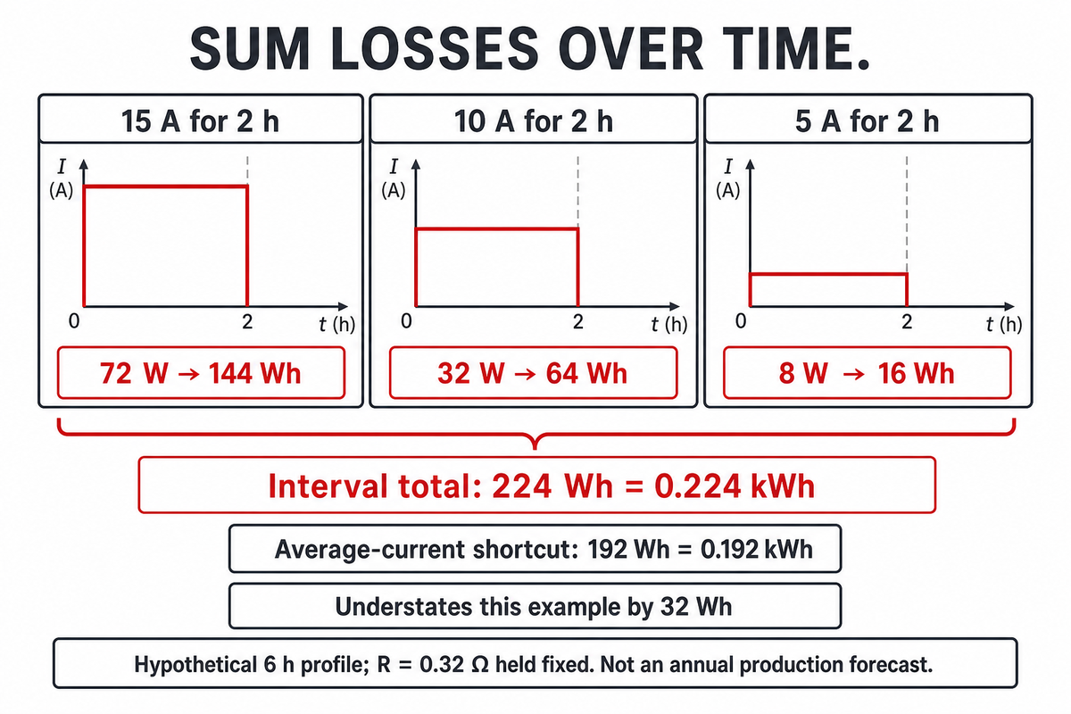
Watts indicate the rate of cable heating at a particular operating point. On the other hand, watt-hours indicate the total loss over time. Resistive heating depends on current squared; therefore, the average current for a given period of time may mask higher current periods. The loss for a given period of time must be accounted for separately.
The 3-State Cable Loss Ledger
Assume a loop resistance of 0.32 Ω, and partition a hypothetical six-hour period into three equal intervals. This example shows a teaching profile, and is not an attempt at solar production forecasting. The intervals are simple to allow an engineer, quality reviewer or a finance colleague to independently verify every calculation.
| Current | Duration | I²R loss | Energy lost |
|---|---|---|---|
| 15 A | 2 h | 72 W | 144 Wh |
| 10 A | 2 h | 32 W | 64 Wh |
| 5 A | 2 h | 8 W | 16 Wh |
| Total | 6 h | Variable | 224 Wh = 0.224 kWh |
The time-average current is 10 A. Using that average alone would give 10² × 0.32 × 6 = 192 Wh, which is 32 Wh below the interval total. The high-current interval contributes disproportionately. That is why a loss model needs a current profile rather than a single attractive operating point.
Now let’s look at a procurement comparison of two equivalent cable options. The buyer has a price per meter and a resistance value for each, but has no annual current profile. The table can help to understand why lower resistance leads to less conductor heat loss. It cannot help to determine the payback period. Finance still requires agreed-upon energy cost, relevant temperature-dependent resistance, and other operating data, to help analyze the energy costs and compare them to the purchase price difference.
The calculation does not account for connection losses, unless that resistance is added specifically. It also does not consider the array’s mismatch and maximum-power-point tracking. The resistance of copper changes with temperature; thus, a fixed value is an approximation. The annual energy yield depends on the complete system. The current-squared relationship follows Sandia’s DC wiring loss model; the current profile above is illustrative. Renewable energy output is unforeseeable from a six-hour teaching case.
Key takeaway
Using a hypothetical 3-State Cable Loss Ledger gives 0.224 kWh of conductor heat loss. Using its average current alone gives 0.192 kWh. Sum interval losses before using a cable calculation in an energy-cost discussion.
Cable size: why AWG cannot settle current capacity
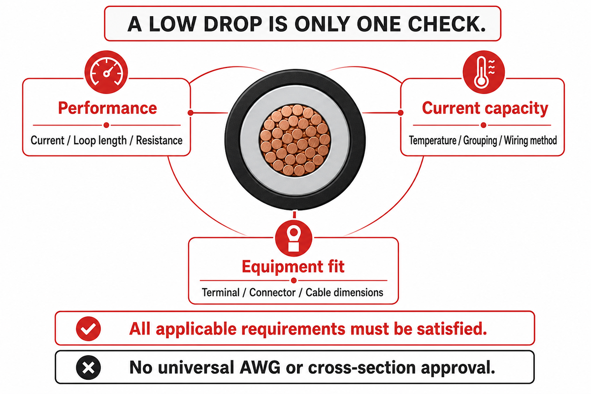
Conductor geometry defines cable size. Allowable current varies for complete installation. Temperature, grouping, wiring method and terminations affect the decision. A conductor that meets a voltage drop requirement may not meet a connection or thermal requirement and vice versa. Safety and performance require separate checks.
How do I choose the right solar cable size?
Choose a solar cable size by checking current capacity and voltage drop separately, then confirming that the candidate fits the equipment and permitted installation. Use the project’s applicable method and consider environmental conditions. An accepted size must satisfy all applicable requirements; an AWG label or low loss alone cannot make this determination.
An AWG wire designation does not determine insulation thickness, sheath diameter, or connector compatibility. A request for “PV wire 10 AWG” still leaves those inputs unanswered. Metric area and AWG are also different size systems; use the actual dimensions of the product. Resistance can be reduced by going to a larger conductor; however, this may require a different terminal, gland or connector contact. The right wire must match the complete connection system.
This matrix separates the questions rather than assigning a universal “correct cable.” In electrical systems, the right cable is the candidate that meets the combined requirements. Installation factors draw from the University of Maryland guidance; the evidence requested is an editorial aid for design, not an alternative to an approved design.
| Question | Needed input | What it can settle |
|---|---|---|
| Which segment carries the current? | String and collection drawing | Correct circuit calculation basis |
| What current must the design allow? | Module data and applicable design method | Required current capacity |
| How hot is the installation? | Ambient and installation temperatures | Relevant temperature correction |
| How are cables grouped? | Actual bundle or raceway arrangement | Grouping effects on heat removal |
| How is the cable installed? | Wiring method and route conditions | Applicable installation provisions |
| What limits the termination? | Equipment and terminal instructions | Connection temperature and size limits |
| What resistance enters the loss model? | Conductor data at the relevant temperature | Voltage drop and conductor heating |
| What is the full current-path length? | Outgoing and return conductor lengths | Loop resistance basis |
| Does the cable fit the connector? | Approved area, strand class and outer diameter | Mechanical and electrical compatibility |
| What exposure is permitted? | Markings and exact product documentation | Sunlight, wet-location and burial suitability |
For example, a design reviewer may see a 0.8% voltage-drop result and still require additional information regarding grouping and termination to accept the size. That is not a contradiction: This does not contradict the result of the calculation. Show both results for the same cable revision, and do not allow Procurement to compare an approved design to an unapproved substitute.
Sizing takeaway: A 0.8% drop result answers one performance question under stated assumptions. It does not approve 4 mm², 6 mm² or any AWG size. Current capacity, equipment fit and installation permission remain separate checks. The Maryland wiring guide explains why installation conditions affect conductor selection.
Why routing and connections can change cable performance
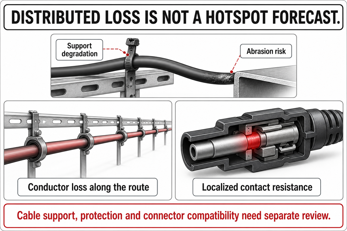
Routing changes conductor length and the environment around the cable; connections add interfaces whose resistance can be concentrated in a small area. Cable support, protective covers and the suitability of connectors along with conductor size need to be considered together. Improving one of those factors may not improve the others.
U.S. Department of Energy’s cable management guidance describes how exposure to high heat and ultraviolet (UV) radiation can cause the plastic ties used to bundle cables to deteriorate, which can then cause the cables to sag and abrade against surrounding surfaces. Exposure to UV radiation and high temperatures also challenge the support materials as well as the cable. A support keeps a cable positioned; a protective wiring method addresses different exposure and damage risks. A neat-looking route can still have an unsuitable bend, unsupported span or vulnerable transition. Exposure to sunlight along the actual route, including exposed and shaded areas, should be reviewed.
Sandia’s PV Connectors project examines contact resistance, localized heating and degradation through field inspections and forensic analysis. A small additional resistance at a contact can dissipate heat in a much smaller region than if the resistance were distributed along a cable. The project does not establish a single field temperature that defines approval or rejection of a given connector.
Now, let’s assume a hypothetical quality review for a cable substitution. The replacement has the same nominal conductor area, but a different outer diameter and strand construction. The loss spreadsheet changes very little, and the approved cable range of the connector may not be correct. The reviewer will only accept assembly, contact and the crimp-tool combination described in the exact instructions for the connector. There are different solar connector types which are identified by their documentation. It is not possible to determine by visual mating if there is electrical compatibility between them, or if they conform to a standard.
Do
- Match cable dimensions to the connector documentation.
- Review support and protection as separate needs.
- Include extra route length in the resistance model.
Don’t
- Approve a connector because its halves appear to mate.
- Treat UV resistance as direct-burial permission.
- Infer safe current capacity from voltage drop alone.
Installation, fault finding and maintenance belong with qualified personnel using the applicable isolation and verification procedures. This manual will not instruct the reader to disconnect or measure energized PV wiring.
Reliability takeaway: The 72 W teaching result is distributed conductor heat, not a connector temperature forecast. A local contact problem needs separate assessment. DOE’s cable-management guidance and Sandia’s connector research show why support, abrasion and connection condition belong beside the electrical calculation.
From cable losses to a project specification
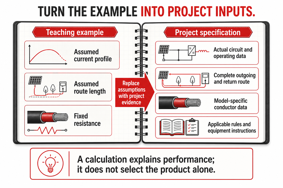
A cable loss calculation aids in establishing assumptions and makes results available for review by the project team. However, it does not pick the product by itself. Solar projects need a consistent basis for comparing the electrical result with product documentation. Check the candidate cable against requirements for installation and equipment, and other relevant considerations.
For example, JINYOU’s H1Z2Z2-K product reference discloses conductor and dimensional data for a constructed cable. Declarations like these should be specific to the model and size. Data for solar applications should not be interchanged between product families merely because their names sound similar. They are not interchangeable with the hypothetical 4 Ω/km input used above, nor are they measurements made for this article.
Resistance is only one factor that determines PV power cable prices. Others include the quantity and type of material, the design of insulation and sheaths, the level of documentation, length of the order, assembly requirements, etc. Only consider copper and aluminum alternatives in cases where the design and terminations of the system allow it. An observed price difference cannot be converted into an energy saving percentage without operating data. Cable weight and the length of the drums also affect the physical supply being compared. Separate purchasing data from the power transmission analysis.
Standards also change. IEC’s catalogue identifies IEC 60364-7-712:2025 as the third edition, published on October 21, 2025, replacing the 2017 edition. That publisher update does not prove which edition a destination jurisdiction has adopted. When preparing a new project specification, confirm the governing edition and equipment instructions rather than copying an older example unchanged.
Project takeaway: Keep the hypothetical 0.224 kWh example as an explanation of interval arithmetic. Replace its assumptions with project data before assessing energy cost. Current installation requirements must be checked separately; the IEC 2025 publication record is a dated standards reference, not evidence of local adoption.
Ready to Match the Calculation to a Cable?
Use JINYOU’s PV Power Cable solutions to progress from circuit to product to project. Keep the electrical assumptions with the enquiry so the cable discussion starts from the same design basis.
Frequently Asked Questions
Is PV wire different than regular wire?
Read the answer
PV wire is specified for a particular photovoltaic application, while “regular wire” doesn’t define a controlled product category. The meaningful comparison is between exact markings, construction and allowed installations. Equal conductor area does not establish equal sunlight resistance, wet-location suitability, voltage rating or connector fit. Compare complete product information before substituting.
Are PV cables suitable for outdoor installations?
Read the answer
Outdoor use cables must have documentation that they are suitable for the exposure conditions. Analyze the effect of sunlight, moisture and temperature as well as mechanical conditions, separately. Outdoor rating doesn’t mean a cable is rated for direct burial, continuous immersion or all allowed methods of installation. Check the marking of the cable and the requirements of the route, including any protected wiring.
Do PV cables require special connectors?
Read the answer
PV cable connections must be compatible with the equipment and approved connector system. Consider the construction of the strands, the diameter of the cable, contact and seal, as well as the tooling, crimp and conductor area. Connector system halves that are similar in appearance may not be compatible. Some circuits terminate at equipment terminals, meaning that there may not be a uniform requirement for all segments of the PV power system.
What materials are used in solar PV cables?
Read the answer
Copper conductors and application-specific insulation and sheathing are commonly found in solar PV cables. The construction may be bare or tinned, based on the product specification.
Does solar PV cable need to be in conduit?
Read the answer
Conduit requirements are determined by the wiring method, location, exposure to physical damage and applicable installation rules. A cable’s PV designation does not solve the issue for the entire route. Review array wiring, building transitions and equipment entry points, as well as support and protection requirements, separately. The chosen method must also be described in the assessment of the circuit’s capacity. Obtain the project-specific ruling from the responsible designer, and don’t apply a universal roof rule.
About the examples: All operating profiles and loss calculations in this guide are hypothetical, and use the stated assumptions. They do not represent JINYOU field-test results, an installation design or forecast annual savings. Institutional sources support the electrical and installation principles, and manufacturer pages support only the products in question. For company background, see JINYOU’s company introduction.
References & Sources
- Working on Solar: Wiring and Fusing University of Maryland Extension.
- DC Wiring Losses Sandia National Laboratories, PV Performance Modeling Collaborative.
- Photovoltaic Cable Testing and Certification UL Solutions.
- IEC 62930:2017 International Electrotechnical Commission, public scope and publication record.
- Solar Photovoltaic Cable Management: Best Practices for DC String Cables U.S. Department of Energy.
- PV Connectors Sandia National Laboratories.
- IEC 60364-7-712:2025 International Electrotechnical Commission, public scope and publication record.