Get in touch with JINYOU Cable Company

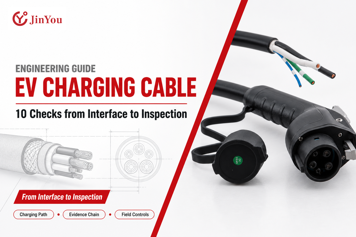
Engineering guide · Reviewed October 2026
A known plug or current label does not show whether a charging lead meets its electrical duty, thermal path, route, environment, evidence scope and field condition. This guide gives engineering, quality, procurement, and operations teams one shared review method.
The short answer: a suitable EV charging cable must match seven connected layers: upstream supply, EVSE, flexible cable, terminations, connector interface, vehicle inlet, and control or communication. Compatibility at one layer cannot approve the other six.
This article provides education support. The existing EV charging cable solution page remains the destination for product configurations, specifications, OEM requirements, and commercial enquiries. Here the focus is on the decision process as to when to validate, what to define and what evidence to request.
Safety boundary: this is not an installation, energized-test, disassembly, bypass, repair, or return-to-service procedure. Charging equipment and vehicle instructions, applicable standards, the authority having jurisdiction (AHJ), site controls and qualified Electrical and Engineering personnel are to be complied with. Public standards pages are cited only for the scope stated.
1. Start with the Charging Path, Not the Cable Name
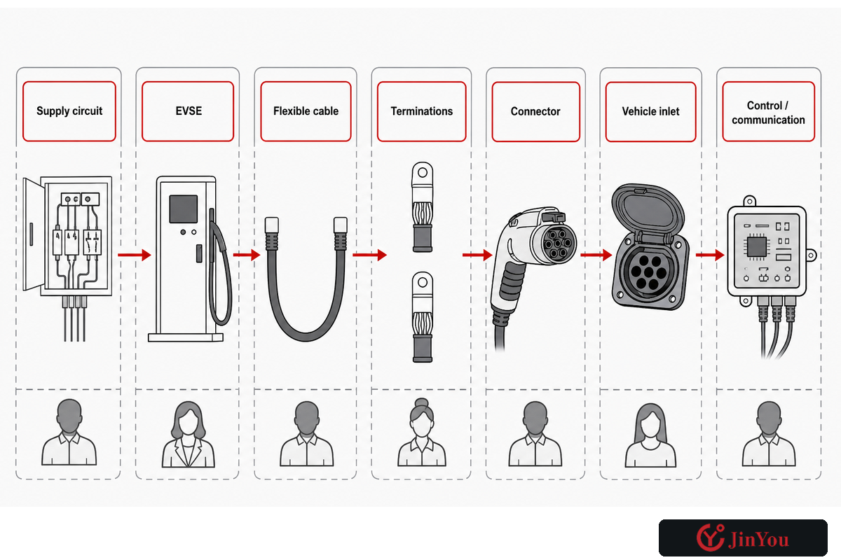
“Charger,” “plug,” and “cable” are often used as if they mean the same object. They do not. That terminology boundary leads to the first practical task: map the complete charging path. The U.S. Department of Energy’s Alternative Fuels Data Center distinguishes charging equipment, connectors, and charging levels; a project should be at least as precise. Otherwise, a requirement can pass from supplier to installer without ownership.
Map the complete power-and-control path prior to discussing a cable. Identify the upstream circuit, the EVSE power and protection functions, the flexible cable, each termination, the mating connector, the vehicle inlet, and the pilot or communication path. Then assign every assumption, evidence item, and field limit to a responsible party. This immediately identifies gaps, for example, a connector has been selected but termination temperature evidence has not been assigned.
| Layer | Decision owner | Evidence to identify | Field boundary |
|---|---|---|---|
| 1. Supply circuit | Electrical design / site | Approved circuit and protection basis | No cable inference from receptacle shape |
| 2. EVSE | Equipment maker / integrator | Equipment rating, control, protection, instructions | Complete-equipment approval is separate |
| 3. Flexible cable | Cable maker / engineering | Construction, standard scope, test records | Match actual duty and route |
| 4. Terminations | Assembly maker | Crimp/contact process and assembly test | Cable data alone is insufficient |
| 5. Connector | Interface owner | Interface family, edition, mating evidence | Fit is not whole-system approval |
| 6. Vehicle inlet | Vehicle maker / fleet | Vehicle compatibility and charging limits | Vehicle can limit the session |
| 7. Control / communication | System integrator | Pilot, sensing, protocol, software dependencies | Physical mating does not prove a session |
This map intentionally places cable at the center. Payments, legal metrology, backend communications, user accounts, remote diagnostics, and cyber security encompass the broader charging service system and appear in Check 10.
2. Connector Families Answer Compatibility, Not the Whole Approval Question
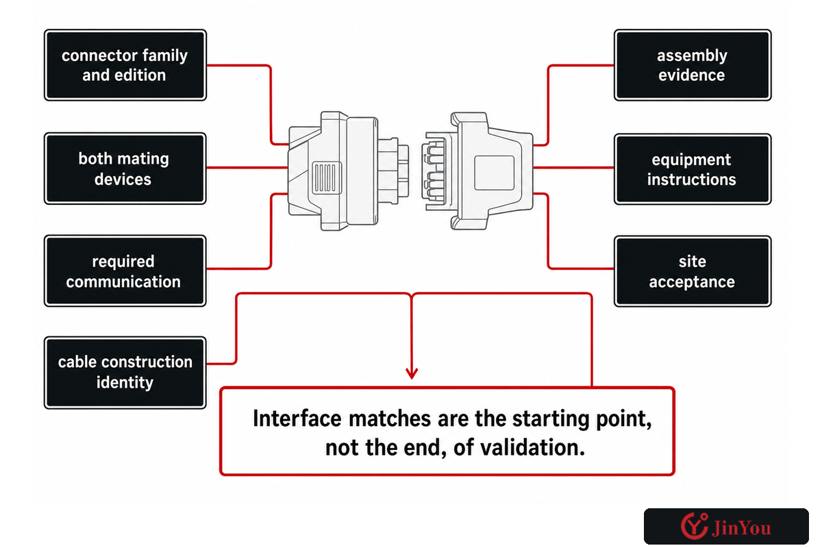
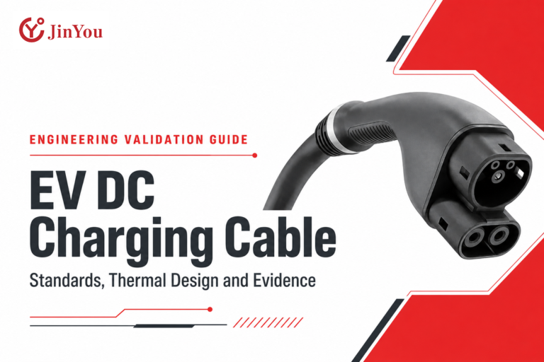
Connector names generally indicate where an assembly can mate, but do not generally describe all the properties of each conductor, insulation, cooling, control, and equipment. Type 1 commonly points to the SAE J1772 AC interface. Type 2 is used for another AC interface family. CCS adds DC contacts to a related interface architecture, while J3400 is the standardized North American Charging System family. These labels generally describe a bounded answer to a question.
The Joint Office of Energy and Transportation’s J3400 guidance describes a North American connector transition while also noting continuing work on certification and interoperability. SAE’s public J3400 family page shows why edition and sub-part matter. A physical change to a charging system interface generally results in a review of construction evidence of cable, but it does not approve or modify installed charging equipment.
Are all EV charging cables the same?
No. Though two assemblies may share a connector family, they can still differ in many ways, such as AC or DC duty, current profile, conductor construction, signal cores, mechanical flexibility, environmental resistance, temperature sensing, active cooling, certification scope, and field conditions. Adapters can solve some mating issues but create new issues regarding compatibility, thermals, and approvals. Interface matches should be considered the starting point, not the end, of validation.
Compatibility checkpoint: record the connector family and edition, both mating devices, required communication, cable construction identity, assembly evidence, equipment instructions, and site acceptance. If any item is unresolved, label the status “conditional” instead of converting a visual fit into a compliance claim.
3. AC and DC Charging Put Different Duties in the Path
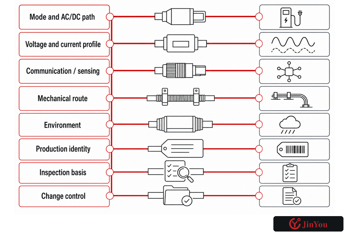
AC charging supplies alternating current to the vehicle, where the onboard charger normally performs power conversion. In DC fast charging, the charging equipment performs the conversion and sends controlled DC to the battery system. That system distinction changes the assumptions around conductors, contacts, communication, temperature monitoring, and, at higher duties, cooling architecture.
Do not select from a kW headline alone. Consider type of charging, system class, continuous charging current, transient peak currents, phase configuration, expected duty cycle, signal communication and control, protective measures, and design of terminations. An electric car owner may see portable Level 2 equipment, brand-specific names, and cable gauge language in search results; none of those shortcuts replaces the system record. A higher-rated cable does not force the EVSE or vehicle to deliver more power, and it cannot correct an unsuitable circuit, routing problem, or incompatible control path.
The UL Solutions EV charging cable testing overview maps cable standards by region and describes available evaluation options. That breadth is useful: the duty question isn’t one number. The final selection of circuit and equipment follows the instructions, where applicable, and qualified design.
| Duty category | Question to freeze | Evidence expected | Status |
|---|---|---|---|
| Mode and AC/DC path | Where does conversion occur and which components carry the output? | System architecture and equipment instructions | Verified / conditional / unresolved |
| Voltage and current profile | Continuous, peak, duration, and limiting device? | Approved load profile and assembly rating basis | Verified / conditional / unresolved |
| Communication / sensing | Which pilot, data, or temperature functions are required? | Interface and control documentation | Verified / conditional / unresolved |
| Mechanical route | Reach, bends, torsion, drag, storage, and handling? | Route drawing plus applicable test evidence | Verified / conditional / unresolved |
| Environment | Temperature, water, UV, fluids, cleaning, abrasion, impact? | Declared service profile and matching evidence | Verified / conditional / unresolved |
| Production identity | Does the supplied build match the tested specimen? | Drawing, BOM revision, marking, report or certificate linkage | Verified / conditional / unresolved |
| Inspection basis | Which scheduled, condition, and event triggers apply? | Maker instructions, site controls, applicable rules | Verified / conditional / unresolved |
| Change control | Who revalidates a revised connector, build, route, or software dependency? | Lifecycle handoff record | Verified / conditional / unresolved |
Measurable fields can use unit-preserving notation, but design recommendations should not be encoded in it. The following values demonstrate how design and records management can control the data and the units of measure. They are not ratings, limits, acceptance criteria, or recommendations. Replace all values with approved project data.
| Field type | Synthetic notation | Authoritative project source |
|---|---|---|
| Nominal / maximum voltage | 240 V / 400 V | Approved system architecture |
| Charging power points | 7 kW / 22 kW | Equipment and vehicle limits |
| Continuous / peak current | 16 A / 32 A | Approved load profile |
| Lowest / highest ambient | -20 °C / 40 °C | Site climate basis |
| Normal / maximum reach | 5 m / 8 m | Route and vehicle study |
| Recorded bend dimensions | 100 mm / 150 mm | Approved construction data |
| Short / long duty window | 3 hours / 8 hours | Fleet operating basis |
| Example review intervals | 30 days / 90 days | Applicable maker or site schedule |
| Connector handling mass | 2 kg / 4 kg | Final assembly data |
| Route clearance | 1200 mm / 1500 mm | Site accessibility plan |
| DC power checkpoints | 50 kW / 150 kW | Charging-system specification |
| Protective response record | 2 sec / 5 sec | Validated control basis |
4. Treat Heat as a Path from Conductor to Ambient
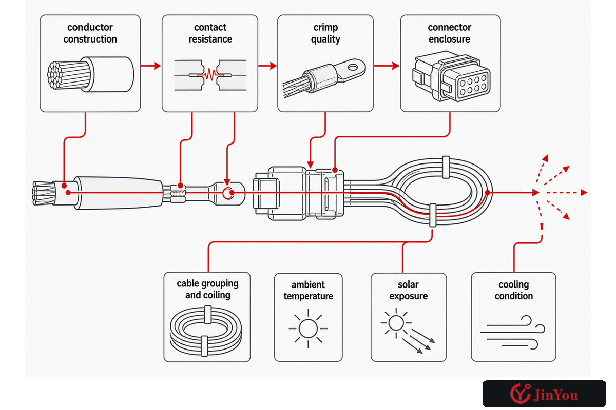
Current Label ≠ Heat-Path Proof. That duty record becomes useful only when the review follows heat through the full assembly. Electrical losses begin in contacts and the surrounding conductors, but the temperature of the path depends on the entire path and surrounding environment. Contributing factors include conductor construction, contact resistance, crimp quality, connector enclosure, cable grouping and coiling, ambient temperature, solar exposure, and cooling condition.
A procurement sheet with “rated current” but no final-assembly temperature-rise evidence is incomplete. You should ask for the specimen tested, terminations fitted, cable routing, the ambient and duty cycles, the locations of temperature measurements, protective controls, and if the production build offered matches the specimen tested. A cable data sheet does not, by itself, explain the thermal behavior of connector, crimp, enclosure, and EVSE assembly.
Uncooled and liquid cooled DC assemblies should not be lumped into a single ranking. Active cooling can change mass and current capability, but it also introduces coolant paths, seals, monitoring, control logic, fault response, maintenance, and additional evidence. A patent describing a liquid-cooled charging cable demonstrates that such architecture exists; it does not prove market adoption, certification, or suitability for a particular project.
There may be some thermal increase within a validated design during operation. Unusual heat, odor or discoloration, repeated derating, a changed fit, fault response, cooling alarms or physical damage are observations for escalation. These observations should be documented on the escalation ladder in Check 9, and should not be artificially limited to a given number.
5. Construction Claims Need a Test Condition
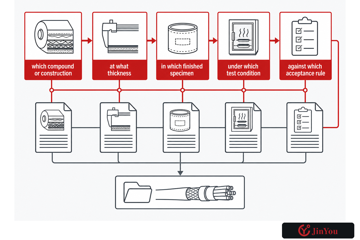
An EV charging cable can combine power conductors, protective conductors, pilot or communication cores, insulation, fillers, reinforcement, shielding where needed, a jacket, and assembly-specific terminations. That thermal review depends on the construction details that carry and dissipate heat. Each element contributes to performance, but material-family names are not guarantees. Saying “TPE,” “rubber,” “halogen-free,” or “UV resistant” does not disclose the actual compound, construction, test method, or acceptance criterion.
Translate each broad claim into a five-part evidence question: which compound or construction, at what thickness, in which finished specimen, under which test condition, against which acceptance rule; then confirm that the evidence applies to the current drawing and production revision. The evidence must also cover flexibility, flame behavior, oil resistance, cold handling, abrasion, shielding, and other relevant performance considerations.
The IEC standard scope pages identify which questions a standard answers. The IEC Webstore entries for IEC 62893-1 and related parts describe boundaries of the EV charging cable family. They do not provide the entire test record or confirm the construction offered by a given supplier. Treat a standard number as an index into evidence, never as a substitution.
Claim
What performance is being promised?
What performance is being promised?
Specimen
What exact construction was evaluated?
What exact construction was evaluated?
Condition
How was it aged, routed, loaded, or exposed?
How was it aged, routed, loaded, or exposed?
Linkage
How does current production match the specimen?
How does current production match the specimen?
6. Route Geometry Is an Engineering Input
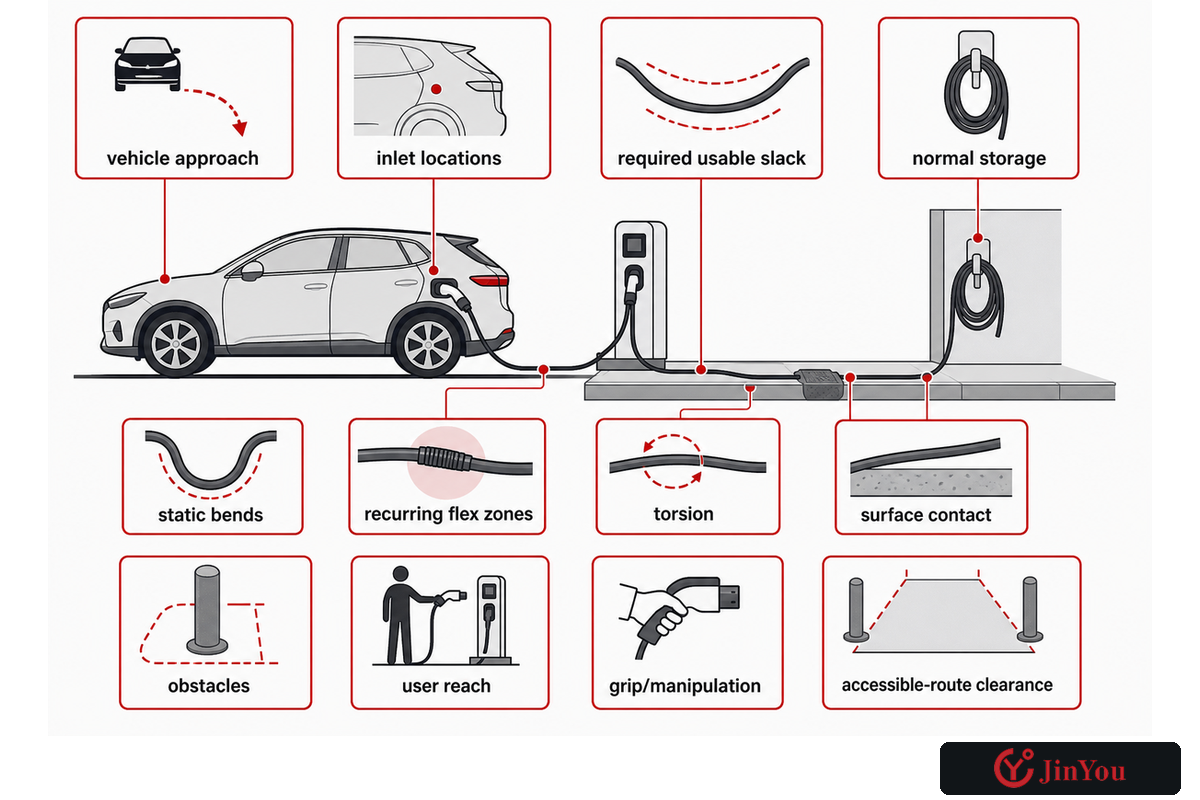
Just because a given cable can reach a vehicle, doesn’t mean it’s right for the route. Separate the installed bend from repeated flexing; distinguish torsion from a simple bend; record dragging, vehicle run-over risk, unsupported length, storage method, connector-side load, and strain-relief movement. A bending path can concentrate stress at a termination, even if mid-span cable looks undamaged.
Consider representative vehicles and inlet positions and don’t automatically assume that every EV has the inlet on the same corner. Check the shortest and longest usable reach, the path around the vehicle, bollards and curbs, the retrieval and storage action, and whether slack creates a trip or traffic hazard. An electrically compatible assembly can remain unusable if a person cannot retrieve, manipulate, connect, and return it safely.
The U.S. Access Board’s EV charging station guidance explicitly connects cable reach and weight with connector operation, vehicle-inlet location, maneuvering space, and accessible routes. It’s a U.S. technical-assistance source, not a universal global code. For each site, identify the accessibility and installation rules that actually apply.
Both cable and the user task have to be considered when evaluating accessibility. Record: vehicle approach, inlet locations, required usable slack, normal storage, static bends, recurring flex zones, torsion, surface contact, obstacles, user reach, grip/manipulation, and accessible-route clearance. If the actual route has not been observed or drawn, mechanical approval is premature.
7. “Outdoor” Is Not a Complete Service Profile
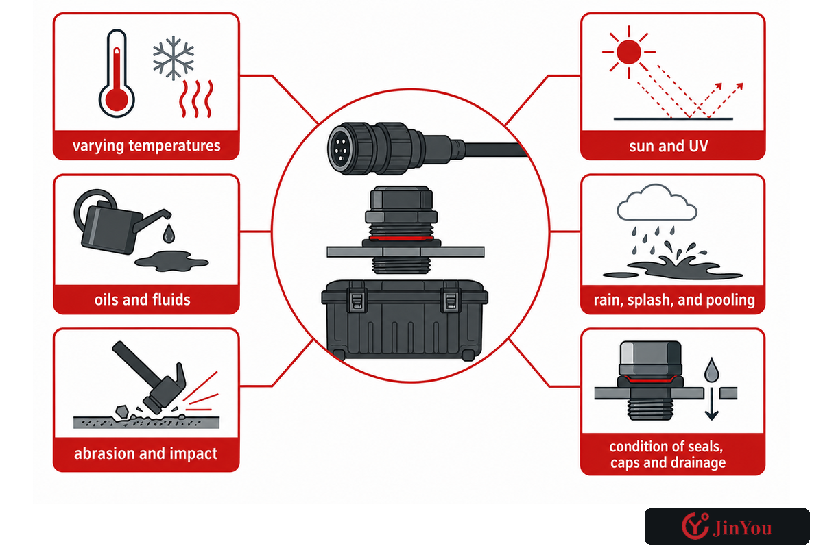
Outdoor use is a bundle of exposures, not one property. Some of these include varying temperatures, the effects of the sun and UV, rain, splash, and pooling; snow and ice; condensation; oils and fluids of the vehicle; salts and other industrial contaminants; cleaning agents and methods; abrasion and impact; crushing and drag; storage; and the condition of seals, caps and drainage. If relevant, include washdown, dusty and chemically aggressive conditions.
Don’t extend an enclosure or connector claim to the whole assembly without supporting evidence. Having an ingress rating on one of the mated components of the assembly doesn’t describe flexible cable, an unmated connector, a damaged seal, the EVSE enclosure, or a field installation. Similarly, having a jacket material marketed for outdoor use doesn’t prove the terminated assembly under various contaminants, temperatures and mechanical conditions.
The UL testing overview cited above identifies available evaluation options within defined cable-standard programs. The AFDC maintenance guidance adds the operational side: cable storage, periodic checks, cleaning, repairs, and troubleshooting affect charging-station condition. Join those two views, design evidence plus maintained field condition, without inventing a universal life or inspection interval.
Service-profile test: if “outdoor,” “weatherproof,” or “heavy duty” cannot be translated into named exposures, conditions, components, test evidence, and maintenance limits, it is still a marketing phrase rather than an engineering input.
8. Read Evidence as a Chain, Not a Logo
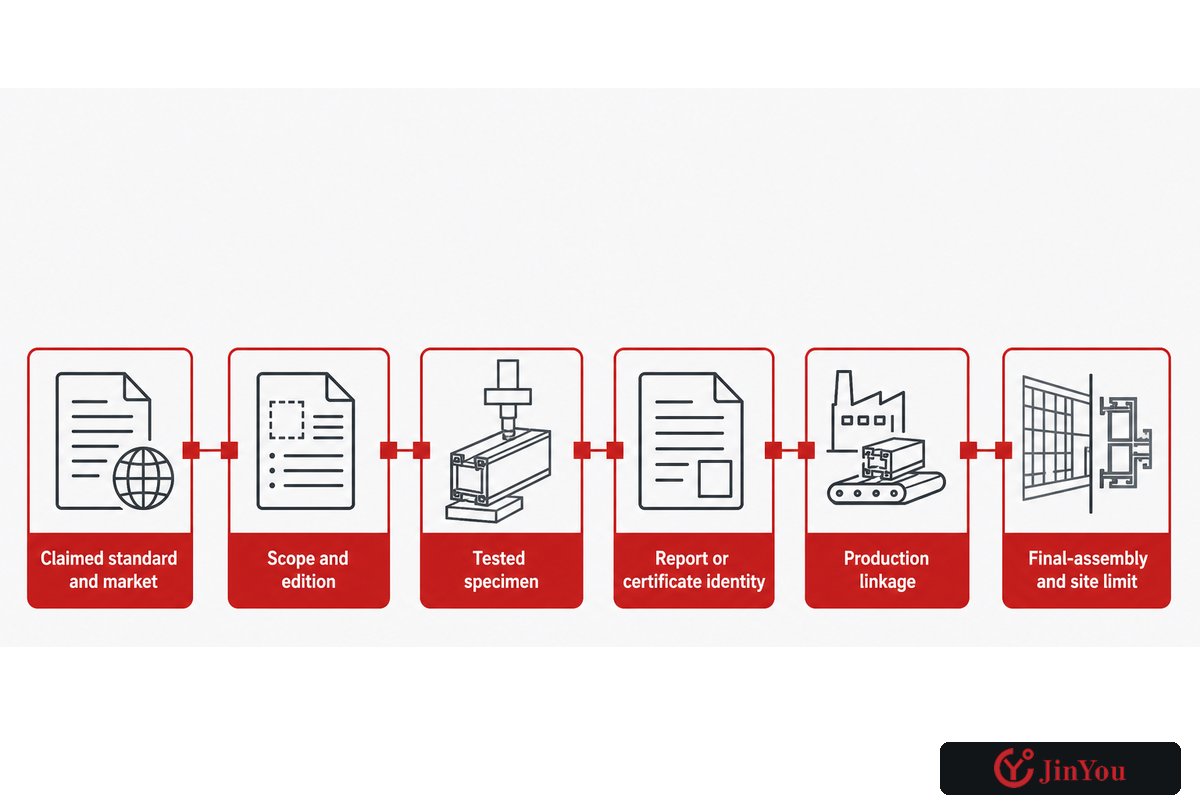
A recognizable mark, laboratory name, or standard number can be useful, only if it relates to the provided construction. That service profile becomes auditable only when each claim is tied to applicable evidence. Read evidence in the order provided.
- Claimed standard and market: what document is named, and is it relevant to the intended jurisdiction and object?
- Scope and edition: does the cited part cover the cable, connector, assembly, equipment, or another layer, and is the edition current for the project?
- Tested specimen: which conductor, insulation, jacket, dimensions, cores, shielding, terminations, cooling components, and markings were evaluated?
- Report or certificate identity: can the identifier, holder, facility, and applicable limitations be verified?
- Production linkage: does the supplied drawing, BOM revision, marking, and process control match the tested specimen?
- Final-assembly and site limit: what remains conditional on terminations, EVSE, routing, installation, or maintenance?
Populate the Duty-to-Evidence Matrix with one of three statuses: verified when evidence applies directly; conditional when a named dependency remains; or unresolved when the evidence or linkage is missing. Do not change “unresolved” to “accepted by similarity.” Using the status language described above provides assurance to procurement, engineering and quality that the correct risk treatment approach has been taken, without misleading the team that every risk can be closed.
Once the educational matrix is complete, product-specific discussions can move to JINYOU Cable’s EV charging cable solutions page. That division is deliberate: this guide owns the evaluation method; the solution page owns configurations and commercial conversion.
Discuss Your Documented Charging Duty
9. Combine Scheduled Inspection with Condition and Event Triggers
A reliable inspection program does not rely solely on a calendar or field condition. It combines maker instructions, site rules, applicable scheduled inspection obligations, routine user observations, and event-triggered, escalation response. AFDC identifies periodic checks, secure cable storage, cleaning, repair, and troubleshooting as general charging-infrastructure maintenance activities. Legal-metrology programs may separately establish inspection dates for public charging equipment. Neither of these sources establishes a single, universal cable interval for all manufacturers and all duty sites.
There can be a crushed, cut, or abraded jacket, swelling or discoloration of the jacket, exposed material, a loose or shifted strain relief, damaged pins or seals, connector fit, contamination or water exposure beyond the approved condition, abnormal heat or odor, cooling warnings, repeated charging interruption, or damage after impact, run-over, pulling, or other abnormal events. The user’s role is to recognize and report, not to open equipment or diagnose energized parts.
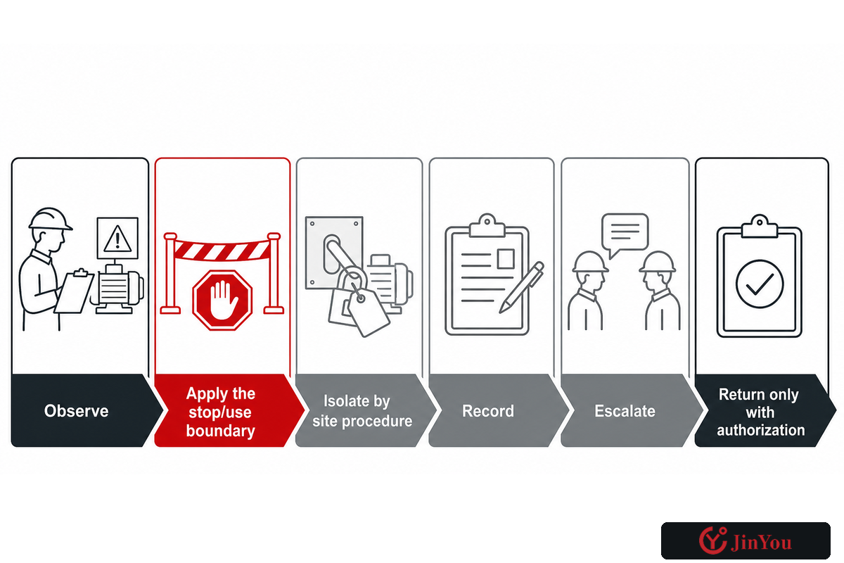
Stop-Use Escalation Ladder
- Observe: identify damage, abnormal behavior, contamination, exposure, or an overdue applicable inspection.
- Apply the stop/use boundary: follow the manufacturer and site rule; do not keep using questionable equipment to “see if it clears.”
- Isolate by site procedure: prevent unintended use without improvising energized work.
- Record: capture equipment identity, location, time, symptom, event, and visible condition.
- Escalate: send the record to the manufacturer-authorized or otherwise qualified assessor.
- Return only with authorization: retain the disposition, repair or replacement identity, checks performed, approver, and date.
Never use a visual check as authority for DIY repair, splicing, bypassing temperature or protective functions, or returning equipment to service. The visible cable may be only one affected part of the assembly.
10. Close the Lifecycle with a Shared Handoff Record
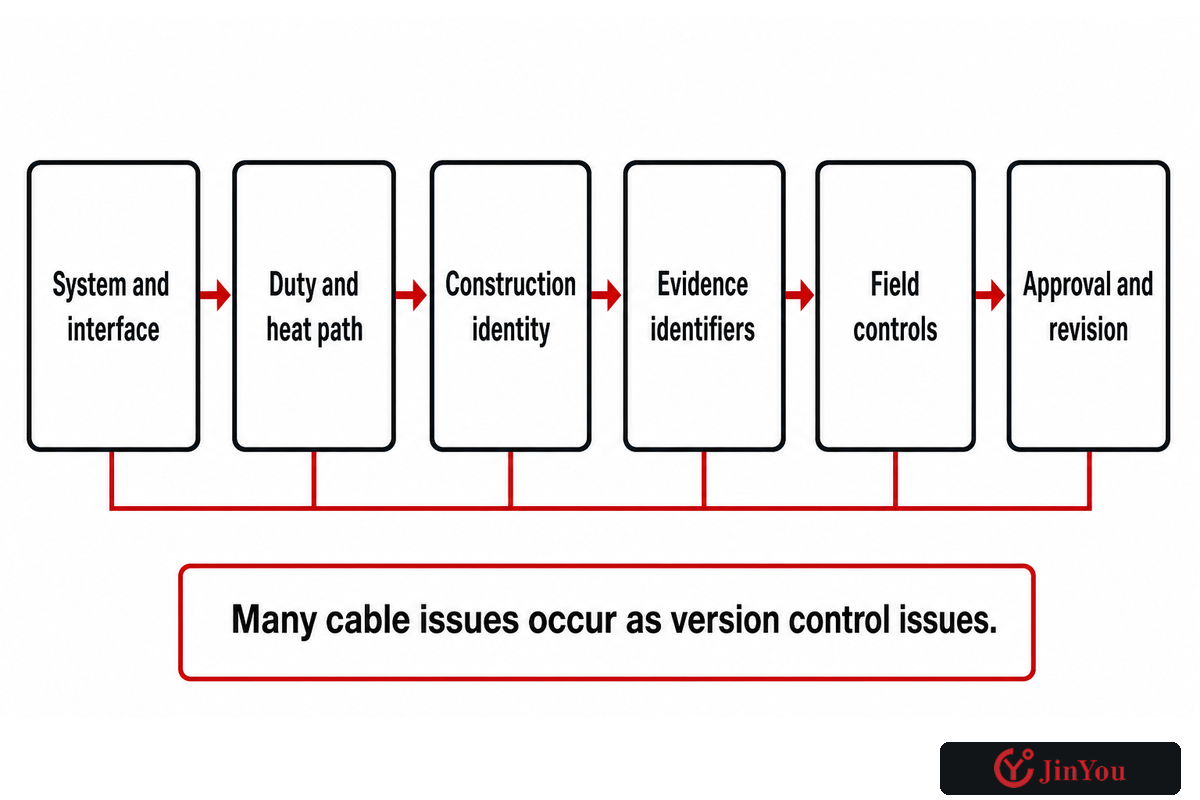
Many cable issues occur as version control issues. Those inspection and stop-use records should enter the same version-controlled handoff. Engineering approves one duty, procurement orders from another description, commissioning receives incomplete evidence, and operations inherits no inspection triggers. A Lifecycle Handoff Record keeping the same controlled basis allows for the transition from design through procurement, commissioning, use, maintenance and change review.
| Record field | What to capture | Change trigger | Owner |
|---|---|---|---|
| System and interface | EVSE, cable, connector, vehicle/inlet, communication | Connector, vehicle, firmware, equipment change | System engineering |
| Duty and heat path | Mode, voltage/current profile, route, ambient, cooling | Load, route, termination, climate, cooling change | Electrical / thermal owner |
| Construction identity | Drawing, BOM, materials, terminations, markings, revision | Supplier or build revision | Supplier quality |
| Evidence identifiers | Scope, edition, report/certificate, limitations | Edition, certificate, or scope change | Compliance / quality |
| Field controls | Storage, inspection schedule, triggers, escalation route | Damage, event, environment, recurring fault | Operations / maintenance |
| Approval and revision | Decision, open conditions, approver, date, next review | Any preceding trigger | Named change owner |
A connector-roadmap change such as J3400 should open a targeted revalidation: which interface, documents, vehicles, equipment, and installed-base assumptions changed? It doesn’t eliminate cable-construction tests and final-equipment evidence. The Joint Office’s reliable-charging discussion also shows that recurring site inspection, cross-vehicle behavior, software changes, backend dependencies, and cybersecurity sit beyond the physical cable.
As such, the cable record must name interfaces to legal metrology, payment accuracy, network protocols, software, diagnostics, accessibility, and cyber security without claiming to approve them. Readers needing additional company and manufacturing context can see the JINYOU Cable Company Profile.
Frequently Asked Questions
Are all EV charging cables the same?
No. They can differ in connector family, AC or DC duty, voltage and current profile, conductor and insulation construction, control cores, mechanical flexibility, environmental resistance, temperature sensing, active cooling, certification scope, and condition. A matching connector only addresses one interface. Two cables that look similar may have different tested constructions, termination processes, route limits, communication functions, or production identities. Confirm the EVSE, vehicle, cable assembly, applicable evidence, site environment, route, and field condition before treating them as interchangeable.
What cable is recommended for an EV charger?
There’s no responsible universal recommendation without the service profile. Start with the approved charging equipment and vehicle instructions, then define interface, AC or DC mode, voltage/current duty, heat path, route and handling, environment, communication, and evidence scope. The equipment maker and qualified project personnel should confirm the final choice under applicable local requirements rather than selecting from connector appearance or a headline current alone.
Can I plug an EV into a 240 V outlet?
The outlet voltage alone doesn’t answer the safety or compatibility question. A compatible charging device, suitable branch circuit, receptacle and connection arrangement, protection, equipment instructions, and local installation requirements all matter. Don’t treat an ordinary extension cord or visual plug fit as approval. Have the circuit and charging arrangement evaluated and installed as required by qualified personnel and the authority having jurisdiction.
What is the difference between an EV charging cable and an extension cord?
An EV charging assembly can include defined connectors, pilot or communication functions, sensing, and protection dependencies. An ordinary extension cord isn’t a substitute. Follow the equipment instructions.
Do EV charging cables get hot?
Current creates losses, so validated systems can have temperature rise. Suitability depends on conductors, contacts, terminations, route, ambient, duty, cooling, sensing, and protection together. Abnormal heat, odor, discoloration, changed connector fit, repeated derating, or cooling warnings should trigger the maker/site stop-use and escalation process, not a DIY limit or repair.
Can an EV charging cable be repaired?
Don’t assume a field splice or cosmetic patch restores the original assembly evidence. Damage can involve conductors, insulation, shielding, signal cores, seals, temperature sensors, cooling paths, strain relief, or terminations. Follow manufacturer-approved disposition and qualified assessment. Return to service only after the authorized process, required checks, and traceable approval are complete.
References & Sources
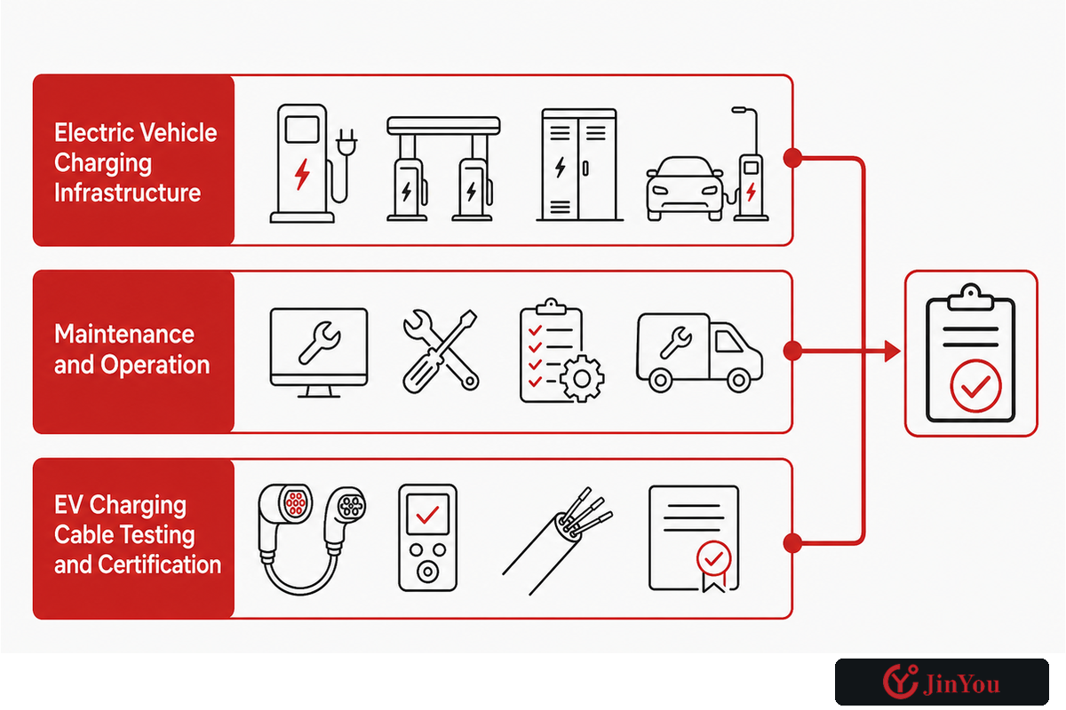
Public pages checked October 5, 2026. Ensure the most recent version and applicability for the project for standards and guidance, as well as connector roadmaps.
- U.S. DOE Alternative Fuels Data Center, Electric Vehicle Charging Infrastructure
- U.S. DOE Alternative Fuels Data Center, Maintenance and Operation
- UL Solutions, EV Charging Cable Testing and Certification
- IEC Webstore, IEC 62893-1 Public Scope
- IEC Webstore, IEC 62893 Family Public Scope
- Joint Office, SAE J3400 Charging Connector
- SAE International, J3400 Standard Family
- U.S. Access Board – Accessible ev charging Station Design Recommendations
- Joint Office, EV Charging Price Transparency and Inspection Context
- Joint Office, Reliable Charging Webinar Transcript