Get in touch with JINYOU Cable Company

Technical buyer guide | Updated September 14, 2026
A PV grounding cable should be identified based on protective function, connection endpoints, governing rules, route, receiving terminals, and installed continuity evidence. Array power and cable colour can’t answer those questions. Sound procurement starts with the complete fault-current path, then works back to the conductor and every interface.
Scope: this guide concentrates on permanently installed protective or equipment-grounding conductors and their bonding handoffs. Temporary protective grounding sets, grounding-electrode system design, and lightning-protection conductors are all separate engineering scopes. Don’t use the sizes or examples below to define those systems.
What Is a PV Grounding Cable?
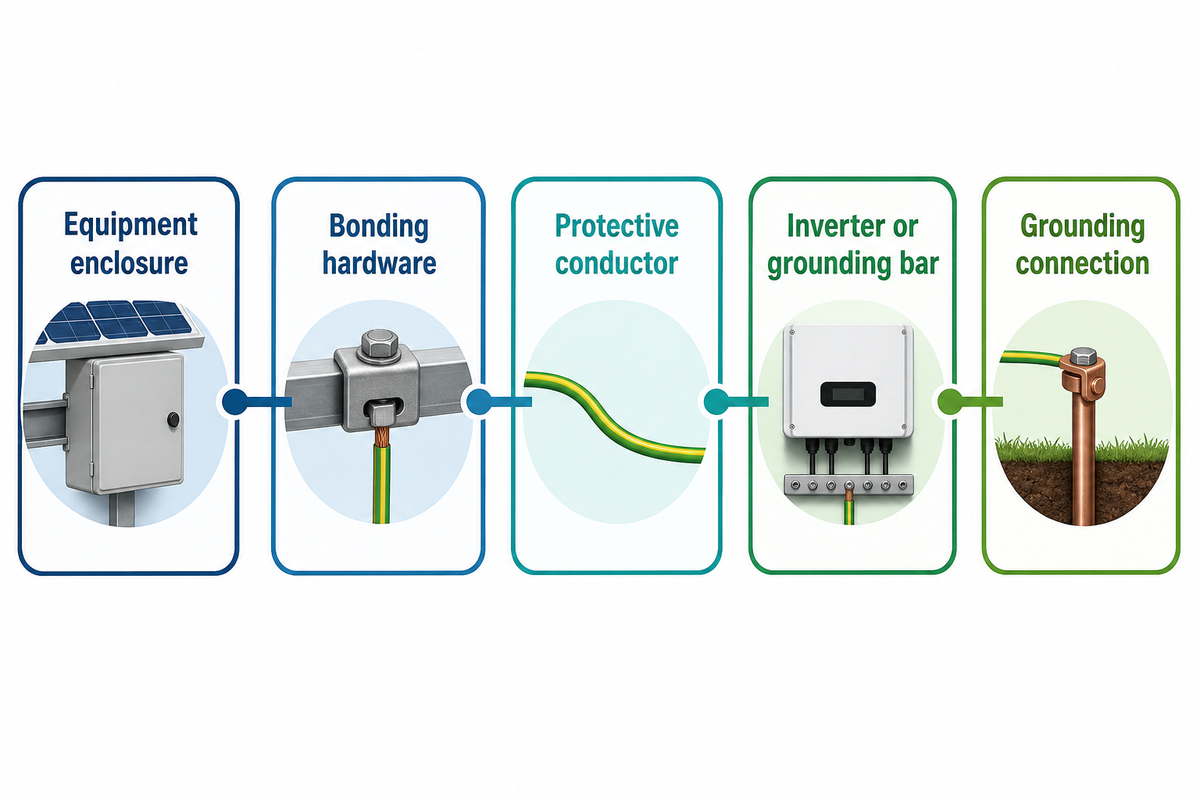
A PV grounding cable is a conductor used in a defined protective path for photovoltaic equipment. It doesn’t carry the normal output of the array. It connects specified exposed metal or equipment grounding points into the fault-current path so the protective design can perform as needed.
A useful path map names five nodes: module frame or equipment enclosure → approved bonding hardware → protective conductor → inverter or grounding bar → the installation’s intended grounding connection. Any break at an arrow can defeat the path even when the copper conductor passes incoming inspection. That path is separate from normal circuit conductors, yet its specification may still need to address overcurrent coordination, flame retardant construction, leakage hazards, UV resistant evidence, PV panels, and any ground rod interface identified by the system design.
Common buying error
Green/yellow jacketing, “solar” wording, or a familiar wire gauge doesn’t identify which two points the conductor must join. Put both endpoints and the conductor role on the drawing before asking for a size.
The Cable-or-Assembly Boundary Table
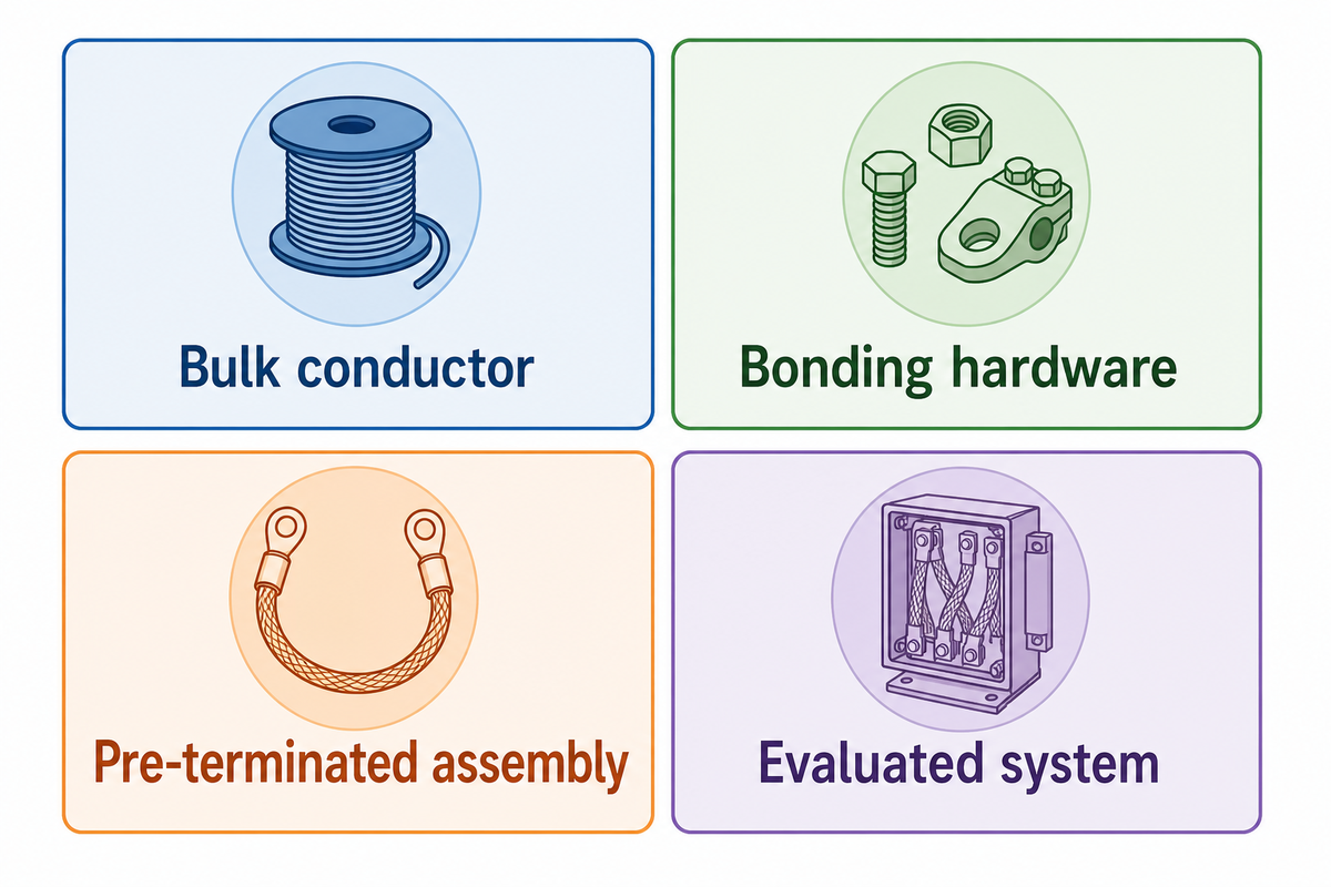
Grounding, bonding, and earthing labels don’t identify one universal product. Searches and requests for quotation may instead say solar grounding, PV earthing, earth grounding, ground cable, earth cable, copper ground wire, green wire, or yellow green conductor; treat each label as an intake term, not a product definition. The endpoints, duty, and adopted array-design basis decide whether the purchase is bulk cable, a short jumper, listed bonding hardware, or an evaluated integrated system. Use this table before any cross-section discussion.
| Line-item type | Connects | Buying unit | Evidence needed |
|---|---|---|---|
| Module-frame jumper | Frame to frame or rail | Pre-terminated assembly | Exact module/rack combination and instructions |
| Racking bond | Rail or purlin interfaces | Clip, washer, lug, or jumper | Evaluated hardware and metal compatibility |
| Equipment grounding conductor | PV equipment to intended grounding path | Bulk conductor or cable | Design size, route, terminal, and installation acceptance |
| Inverter protective-earth lead | Named terminal to project grounding point | Cable plus terminal | Equipment manual and terminal range |
| PV direct-current circuit cable | Modules, strings, combiner, inverter | Current-carrying PV cable | Separate circuit, voltage, current, route, and product evidence |
| Grounding-electrode conductor | Defined system point to electrode system | Separate design scope | Adopted rules and project design |
| Temporary protective ground | De-energized work zone connections | Worker-protection grounding set | Fault duty, work procedure, clamps, and competent control |
| Lightning-protection conductor | Air termination, down conductor, earth termination | Risk-based protection system | Lightning-risk design and separation/bonding decisions |
| Integrated grounding system | Specified modules, supports, hardware, and path | Evaluated system | Complete system boundary and installation instructions |
An unqualified line item of “one lot of solar earth wire” should be rejected in the procurement process. Ask the designer to choose the row, define both endpoints, and name the evidence owner. This small step prohibits a bulk-cable quotation from being interpreted as a finished bonding assembly.
Where the Grounding Path Runs in a PV System
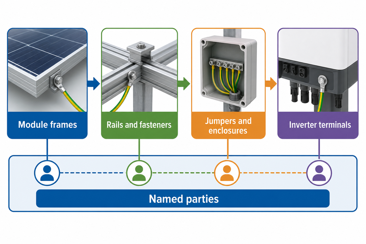
The grounding path crosses more interfaces than a cable schedule typically displays. Module frames, rails, fasteners, jumpers, enclosures, inverter terminals, grounding bars, and the installation grounding system can belong to disparate suppliers/trades. Indicate ownership at every handoff point on the single line drawing.
- Identify each exposed conductive part and the approved bonding method.
- Show where a listed or approved assembly substitutes a separate conductor.
- Assign the cable, lug, crimping or torque record, and inspection to named parties.
- Mark the transition between copper, aluminum, galvanized steel, stainless steel, and coated surfaces.
- Define where the final connection is located along the installed path along with the acceptance record for that path.
Rooftop routes can look simple on a bill of materials while crossing dozens of frame and rail joints. Utility-scale plants repeat the same interface many more times. Repetition raises the value of a standard breakpoint record; it does not turn one cable certificate into proof for every joint.
Which Rule Set Governs the Cable and Installation?
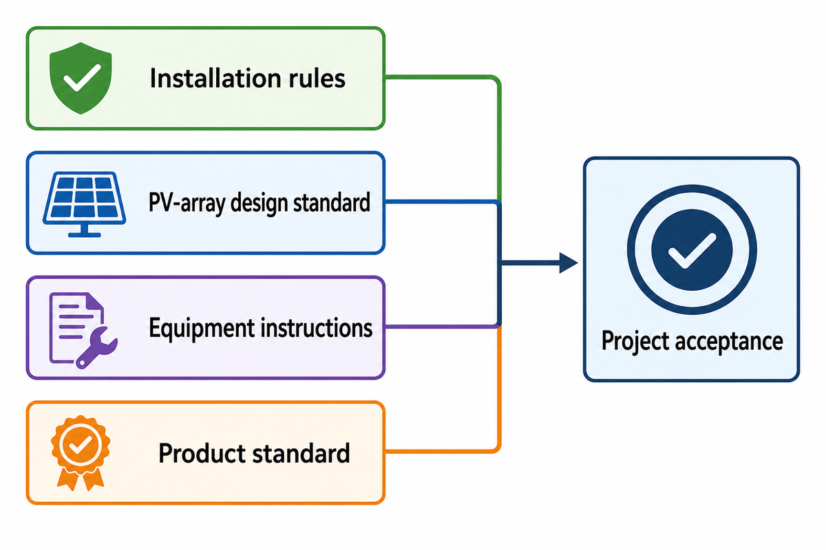
No single document proves the cable, installation, and local acceptance at once. IEC 60364-7-712:2025 focuses on the PV electrical systems and on the PV equipment and their installation, including selection and application. Meanwhile, IEC 62548-1:2023 and Amendment 1:2025, in a separate document, address design of the PV array, wiring, and earthing.
| Question | Document function | Can establish | Cannot establish alone | Owner |
|---|---|---|---|---|
| How is the PV installation arranged? | Adopted installation rules | Installation duties and selection context | A specific cable certificate | Designer / local authority |
| How is the array designed? | PV-array design standard | Array wiring, protection, switching, and earthing scope | Local adoption or product conformity | PV design engineer |
| Will the receiving terminal accept it? | Equipment instructions | Material, size, preparation, and terminal method | Other equipment or routes | Equipment supplier / installer |
| Does the cable have the requested rating? | Product standard and certificate/test evidence | Exact product construction and tested scope | Installed continuity | Manufacturer / quality |
| Is the project accepted? | Contract, approved drawings, inspection, local rules | Project-specific disposition | Universal acceptance elsewhere | Project authority |
Specify the basis of adoption and the edition. The IEC public catalog identifies the 2025 third edition of IEC 60364-7-712 and a 2025 amendment consolidated with IEC 62548-1:2023. The summary of the public evidence helps route that evidence; it neither reveals nor replaces paid sections. In United States discussions, NEC, 250.122, EGC, AHJ, 10 AWG, 6 AWG, and THHN wire may appear in search results; none is a standalone size instruction for this project.
What Size PV Grounding Cable Do You Need?
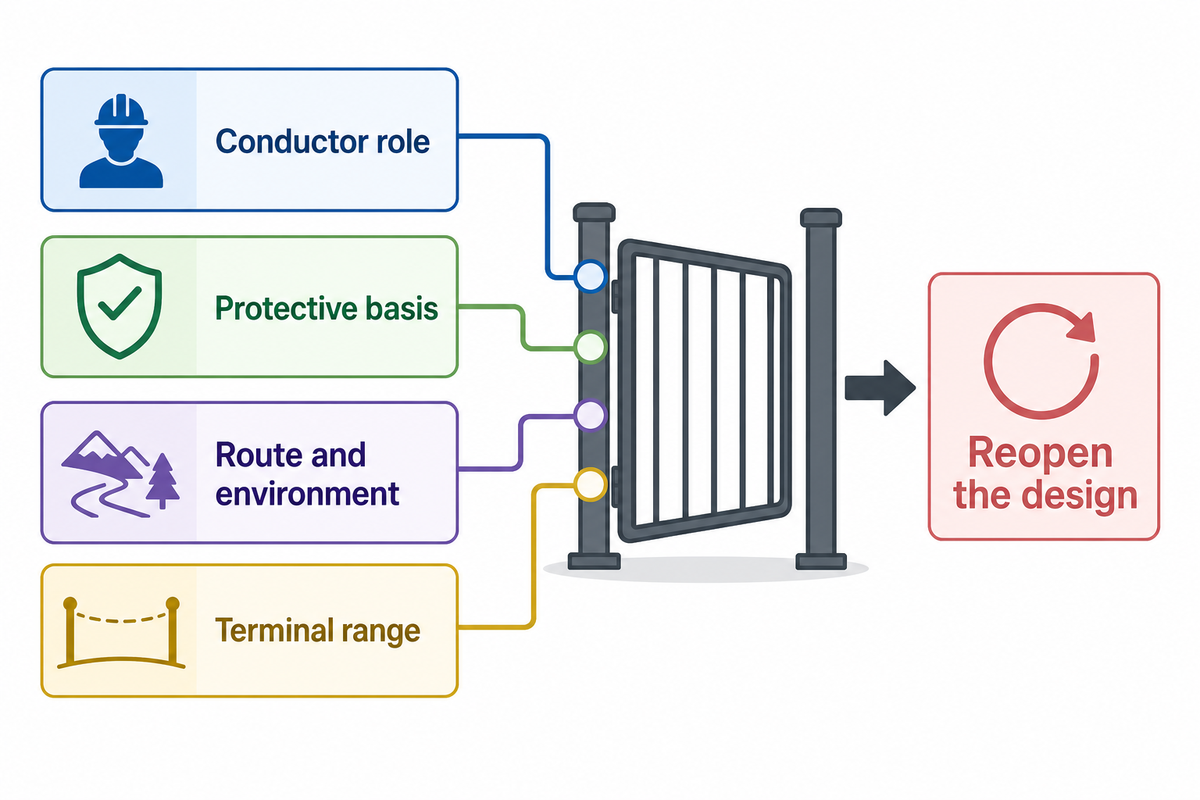
There is no responsible kilowatt-to-ground-wire-size conversion. A 10 kW rooftop array and a 10 kW ground-mounted system can have different conductor roles, routes, protection, equipment, and jurisdictional rules. Select the method first, then calculate or check the size under the applicable array-design basis.
Nine-Trigger PV Grounding Change-Control Card
| Trigger | Why the old choice may fail | Evidence to reopen | Decision owner |
|---|---|---|---|
| 1. Conductor role changes | Sizing basis and endpoints change | One-line and rule basis | Electrical engineer |
| 2. Governing edition changes | Requirements or definitions may move | Code/standard register | Designer / authority |
| 3. Protective basis changes | Fault duty or coordination can change | Protection study | Protection engineer |
| 4. Material changes | Resistance and termination compatibility differ | Calculation and lug data | Engineering / quality |
| 5. Route changes | Length, exposure, and protection change | Route drawing and environment | Construction lead |
| 6. Mechanical protection changes | Exposed conductors face different damage risk | Wiring method and support details | Installer / inspector |
| 7. Terminal or equipment changes | The conductor may no longer fit | Manual, terminal range, tooling | Equipment owner |
| 8. Environment changes | Wet, UV, chemical, or burial evidence may be absent | Exact product test scope | Quality / manufacturer |
| 9. Operating mode changes | Hybrid or island operation may change earthing state | Mode table and switching sequence | System engineer |
What wire size should I use when earthing my solar panel frame?
Don’t select from panel wattage or a forum gauge. Determine if the connection is a frame bonding jumper, equipment grounding conductor, or other roles. Then apply the adopted sizing rule with the protective basis, conductor material, route, physical protection, terminal range, and equipment instructions. Send the resulting cross-section and its calculation or table reference to procurement. Local designers or installers must confirm the final choice.
JINYOU PV Grounding Cable Specification Boundary
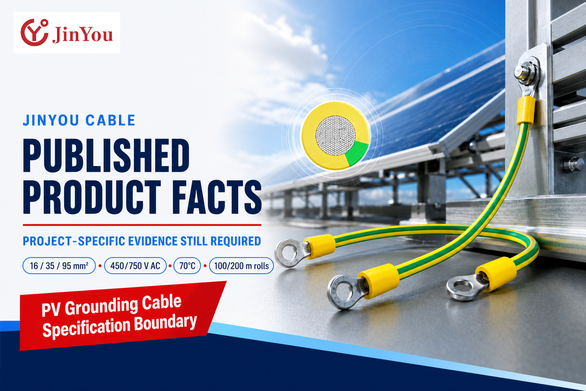
The JINYOU product page supplied for this project states a bounded set of construction and supply facts, not an independent certification or universal project approval. It describes a flexible copper conductor with PVC construction in 16, 35, and 95 mm² sizes. It states 450/750 V AC, 70°C maximum conductor operation, and 250°C for 5 seconds in its short circuit text.
| Published fact | Open project question | Evidence to request |
|---|---|---|
| 16 / 35 / 95 mm² | Which size does the design require and terminal accept? | Design basis plus receiving-terminal data |
| 450/750 V AC | Does the project require a different voltage basis? | Circuit and product-standard match |
| 70°C operating value | Are equipment and route temperatures compatible? | Thermal design and exact product data |
| 100/200 m rolls; 100/500/1,000 m drums | How will cut lengths, waste, and traceability be controlled? | Length schedule and packing plan |
The page also states 10–20 days after specification, packaging, and quantity approval. It expressly says the published values do not establish outdoor, wet-location, direct-burial, ultraviolet, oil, ozone, salt-mist, or chemical ratings. Check the JINYOU PV grounding cable specifications, and obtain the exact evidence that your route requires.
Bare or Insulated Copper, and Which Route?
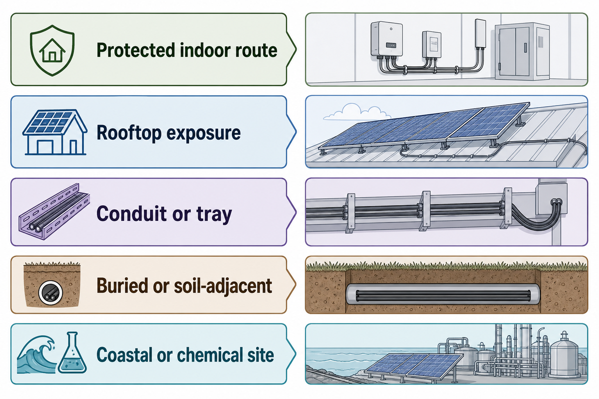
Choose construction after the route and exposure are fixed. Different situations may allow bare or insulated copper, but material alone can’t prove suitability for sunlight, water, soil, chemicals, abrasion, movement, and identification. A cable assembly may also involve a connector, clamp, sheath, tinned copper, bare copper, copper PV wire, or another solar cable construction, so the exact size and type still need route-specific evidence. The installed environment must agree with documented product and wiring method authorizations.
| Route condition | Question to close | Evidence |
|---|---|---|
| Protected indoor route | Identification, temperature, wiring method | Product data and adopted installation rule |
| Rooftop exposure | UV, heat, water, support, sharp edges | Weathering and installation evidence |
| Conduit or tray | Fill, grouping, pulling, drainage, bonding | Route calculation and support method |
| Buried or soil-adjacent | Direct-burial permission, moisture, corrosion, protection | Explicit burial rating and civil detail |
| Coastal or chemical site | Salt, chemicals, condensation, mixed metals | Site assessment and material compatibility |
Which wire is best for solar earthing?
The best wire is the one that satisfies the defined conductor role, adopted rules, fault or protective basis, route exposure, mechanical protection, and terminal instructions. Copper may solve conductivity and termination needs, but insulation colour or a copper conductor does not prove UV, wet, burial, chemical, or corrosion suitability. Record the route exposure on the roof. Request evidence of the product that corresponds to this exposure.
Prior to the cable release, for work on an exposed roof, evidence of roof top route exposure should be recorded.
Terminations Can Invalidate a Correct Cable Choice
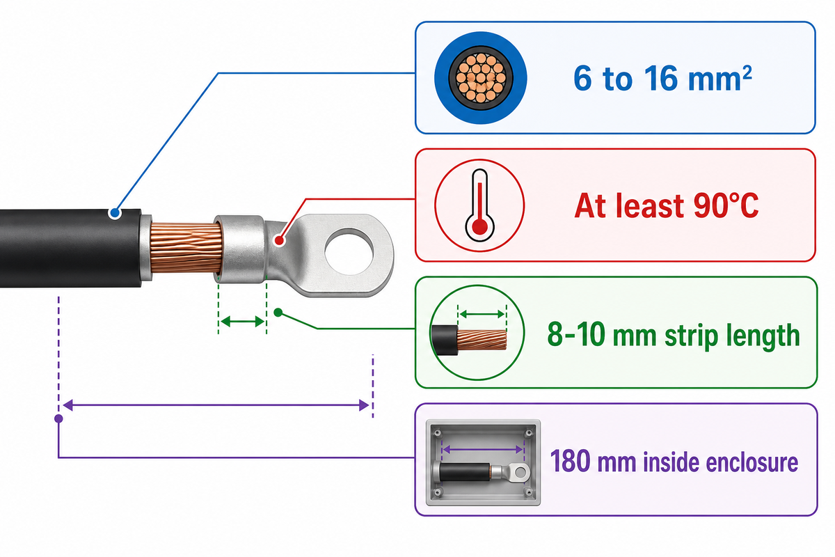
A conductor is only considered adequate if both the receiving terminal and the method of installation are acceptable. Cross-section, copper type, strand construction, insulation strip length, temperature rating, terminal material, plating, torque or crimp tooling, and environmental scope form one assembly. Even a larger conductor may be inadequate for a given terminal.
One published inverter instruction example accepts copper, solid or stranded grounding conductors from 6 to 16 mm², requires at least 90°C, gives an 8–10 mm strip length, and limits the conductor length inside the enclosure to 180 mm. These values apply only to that equipment, and they provide a clear handoff example: JINYOU’s 35 and 95 mm² options cannot simply be assumed to fit.
“The Earth is not to be considered an effective ground-fault current path.”
Compatibility decision
Pass only when cable and terminal data agree. Clarify when strand class, plating, or environmental scope is missing. Reject the handoff when cross-section falls outside the terminal range or the required installation method is prohibited.
Build a Fault-Path Breakpoint Register
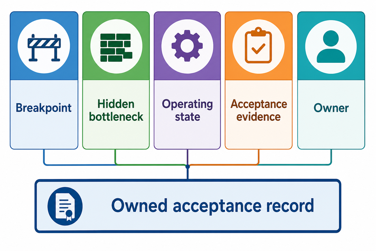
The Fault-Path Breakpoint Register turns hidden interfaces into owned acceptance records. The Department of Energy shows how fastener, lug, galvanized purlin, aluminum frame, stainless hardware, coatings, crevices, and moisture can weaken a bonding path. None of these failure points appear on a cable certificate.
| Breakpoint | Hidden bottleneck | Operating state | Acceptance evidence | Owner |
|---|---|---|---|---|
| Module frame to clip | Coating penetration and approved combination | All valid modes | Part ID and installation check | Installer / quality |
| Clip to rail | Surface treatment and seating | All valid modes | Visual/installation record | Installer |
| Rail splice | Bonding across mechanical joint | All valid modes | Approved splice or jumper record | Racking contractor |
| Rail to lug | Dissimilar metal and trapped moisture | All valid modes | Material and torque record | Quality |
| Lug to conductor | Strand/range/tool mismatch | All valid modes | Crimp or torque evidence | Electrical installer |
| Cable route transition | Abrasion, water, or burial boundary | All valid modes | Route inspection | Construction lead |
| Cable to inverter terminal | Cross-section, strip, temperature | Grid and island modes | Manual and termination record | Commissioning |
| Mode-change device | Earthing state and switching sequence | Grid / island / stand-alone | Functional sequence test | System engineer |
| Grounding bar handoff | Ownership gap between packages | Each defined mode | Connection and continuity record | Project authority |
One example of a work record might be “BP-07, 16 mm² copper to inverter PE terminal, grid and island modes, terminal range confirmed, 9 mm strip length recorded, inspection complete, commissioning owner.” This entry illustrates the necessity to define the inspection and test method for each project.
Use JINYOU’s pages to prepare the cable evidence file and trace the supplied batch and acceptance records. Those records support the cable package; the installed breakpoint register closes the field handoffs.
RFQ Handoff for PV Grounding Cable
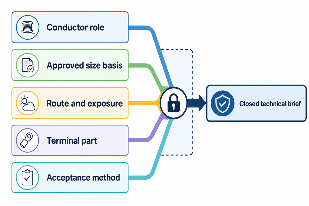
A useful request for quotation should make clear the protective function and evidence boundary before quantity and delivery. Suppliers can respond to a closed technical brief; they can’t, in good faith, infer the conductor role, the adopted installation rule, the exposure conditions, terminal acceptance, or the project approval from colours and metres.
Ten fields to lock
- Destination market, adopted rules, editions, and approving party.
- Conductor role and both connection endpoints.
- Approved size basis, conductor material, and strand construction.
- Colour, marking, insulation, and required product evidence.
- Route, exposure, mechanical protection, and support method.
- Lug or terminal part, range, plating, preparation, and tooling.
- Inspection, continuity/acceptance method, and record owner.
- Required length, cut schedule, spare policy, and traceability unit.
- Packaging, drum/roll constraints, marking, and delivery location.
- All nine change triggers and the person authorized to reopen the design.
Before sending the enquiry, check whether the cable scope fits your project, review the published size lookup, and estimate order length and package quantity. Treat those tools as intake support, not engineering approval.
What 2025–2026 Signals Mean for Buyers
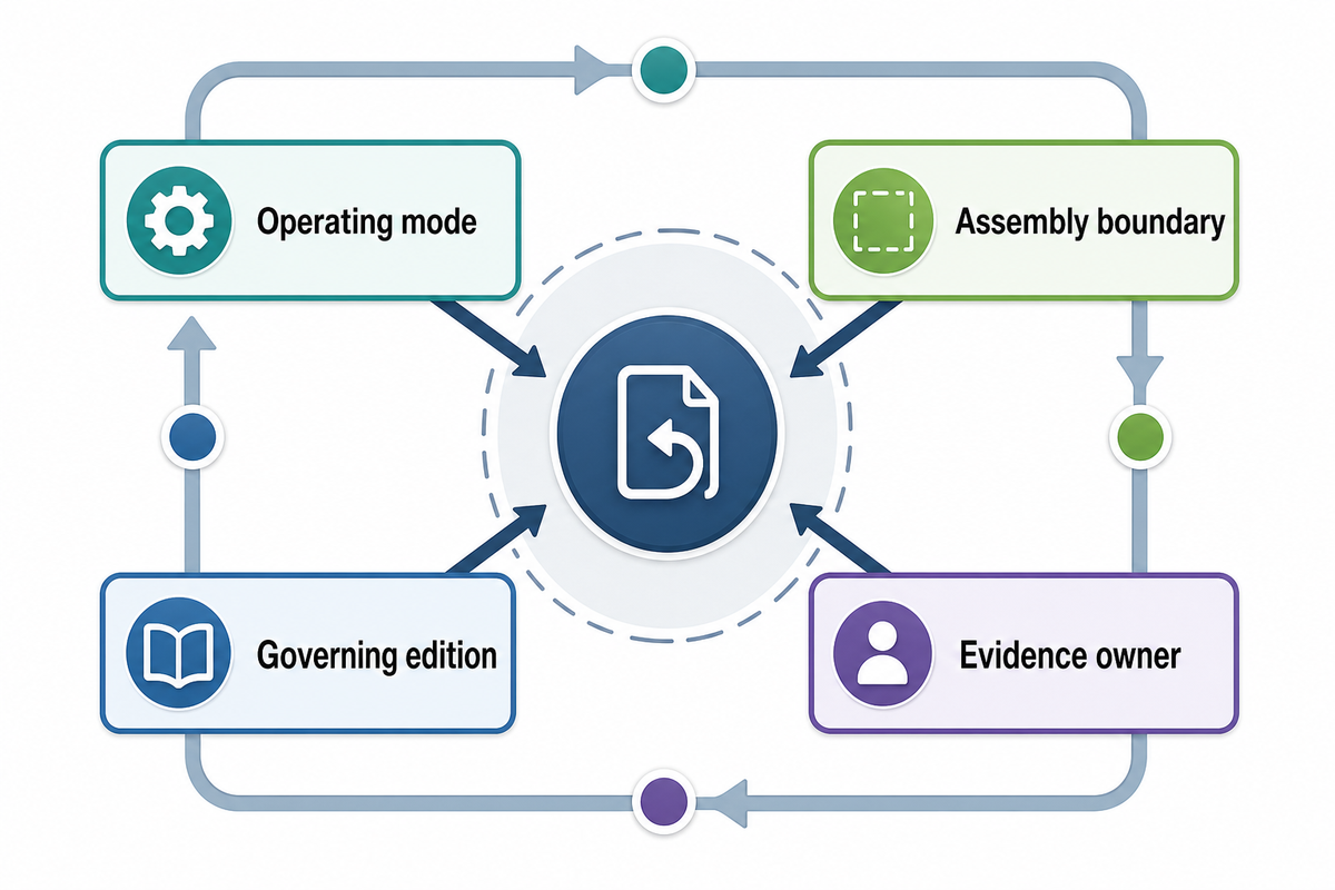
Current signals point to tighter system-boundary and operating-state control, not a generic cable-growth story. The 2025 IEC changes address PV systems and the design of the arrays, and make the function of the related documents clearer. The 2026 amendment concerning prosumer systems highlights changes to system earthing when the operating mode changes.
A 2025 study reported a 6.7% reduction in measured resistance for a nine-module example. Its full-system installation scenario estimated 585 seconds for the tested grounding-clip approach versus 945 seconds for the comparison method, a 38.1% reduction. These data pertain to this scenario and test configuration, showing why integrated assemblies deserve evaluation rather than why every project should abandon a separate conductor.
The 2025 Lawrence Berkeley National Laboratory dataset covers 1,760 United States utility-scale projects larger than 5 MW AC installed through 2024. Portfolio-level breakpoint records and change control help reduce ambiguity when a handoff occurs. The dataset does not quantify grounding-cable demand or indicate commercial growth.
Buyer action for 2026
Add operating mode, assembly boundary, governing edition, and evidence owner to the quotation package. Reopen the path review when switching architecture, equipment, or integrated grounding hardware changes.
Frequently Asked Questions
Short answers still need a conductor role and project boundary. The answers below address permanent PV grounding and bonding. They do not replace the adopted rules, equipment instructions, engineering design, installation procedure, or local inspection for a specific project.
Do solar panels need a ground wire?
Answer
PV equipment and exposed conductive parts need the grounding or bonding treatment required by the adopted installation rules and equipment instructions. That doesn’t mean every module always receives an identical separate wire. Some approved racking or bonding systems create continuity through evaluated hardware. The designer must identify each bonding point, conductor role, and connection method, then the installer must follow the applicable instructions.
How do you ground a PV system?
Answer
Identify required bonding points and system connections, choose approved hardware or conductors, size and route them under the governing design, match every terminal, then inspect and test the completed path. Hybrid or islandable systems also need each valid operating state documented. Qualified designers, installers, and the local authority control the project-specific method.
What happens if you do not ground solar panels?
Answer
Missing or broken protective paths can leave exposed metal at a hazardous potential during a fault and can prevent the protective design from operating as intended. The exact result depends on the system architecture and fault. That’s why acceptance must cover the full path across frames, hardware, conductor, terminals, and the intended system connection.
Should a solar inverter be grounded?
Answer
Follow the inverter instructions, adopted electrical rules, and system design. Don’t substitute a generic internet gauge, lug, or grounding point for the equipment’s specified terminal and method.
What must be specified for a solar panel box grounding cable?
Answer
Identify the box and terminal, the conductor role and endpoints, the protective or fault basis, route, environment, required size, material, strand class, and governing document. Add the approved lug or terminal method and acceptance record.
What is the difference between grounding cable and earthing cable?
Answer
The words vary by region and standard. “Grounding cable” may describe an equipment grounding conductor, while “earthing conductor” may describe a conductor connected to an earth electrode or a protective earthing function. Don’t translate the label into a product automatically. Record the two endpoints, normal and fault duty, adopted terminology, and installation evidence. Those fields reveal whether the purchase is bulk cable, a bonding assembly, or another system component.
Can I use 12 AWG wire for a grounding wire?
Answer
There’s no universal yes or no. Confirm the conductor role, applicable sizing rule, fault/protective basis, material, route, physical protection, terminal range, and jurisdiction. The responsible designer or installer must approve the final size.
Send a Locked Specification, Not a Guess
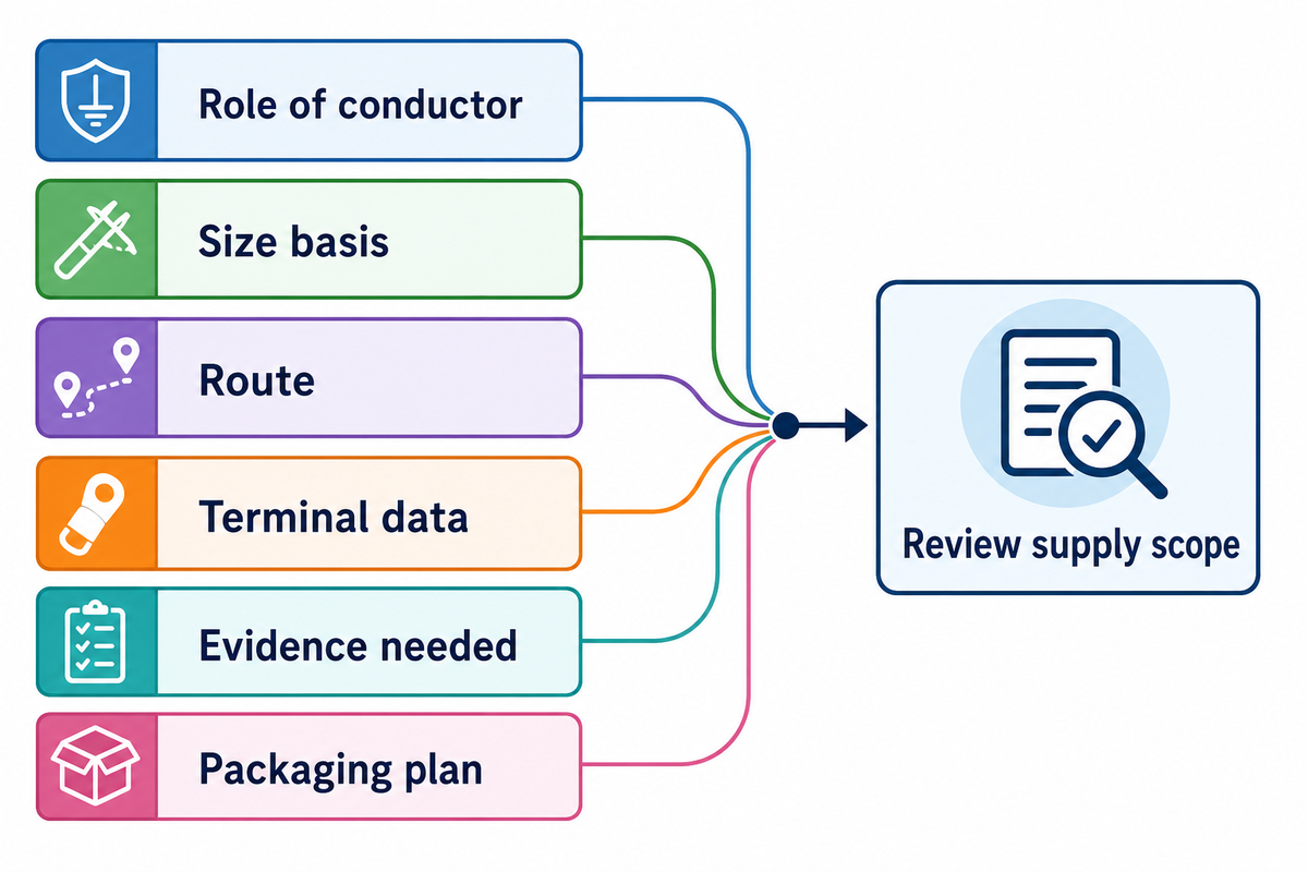
JINYOU Cable designs and manufactures cable solutions for solar power, energy storage, and electric vehicles. For a PV grounding cable quote, include the role of conductor, the size basis, the route, the data for the terminals, the evidence needed, quantity, and your packaging plan. JINYOU can review the supply scope against the applicable array-design basis; final project acceptance remains with the responsible designer, installer, and local authority.
How This Guide Was Built
The JINYOU Cable technical team prepared this specification guide from public product information, official safety and standards scopes, equipment instructions, and current PV field guidance. No private defect rate, customer result, certification, or unpublished factory test was added. Every project still needs its own approved design and evidence package.
References & Sources
- OSHA 29 CFR 1910.304, Wiring Design and Protection.
- OSHA 29 CFR 1910.269, grounding for Employee Protection.
- U.S. Department of Energy, Managing and Mitigating Solar PV Corrosion.
- IEC 60364-7-712:2025 official catalog record.
- IEC 62548-1:2023 plus Amendment 1:2025 official catalog record.
- IEC 60364-8-82:2022 plus Amendment 1:2026 official catalog record.
- IAEI Magazine, On the Grounding and Bonding of Solar Photovoltaic Systems.
- Applied Sciences 2025 grounding-clip study.
- Lawrence Berkeley National Laboratory, U.S. Utility-Scale Solar 2025 Data Update (1).