Get in touch with JINYOU Cable Company

Updated September 2026 · Written by Cherry
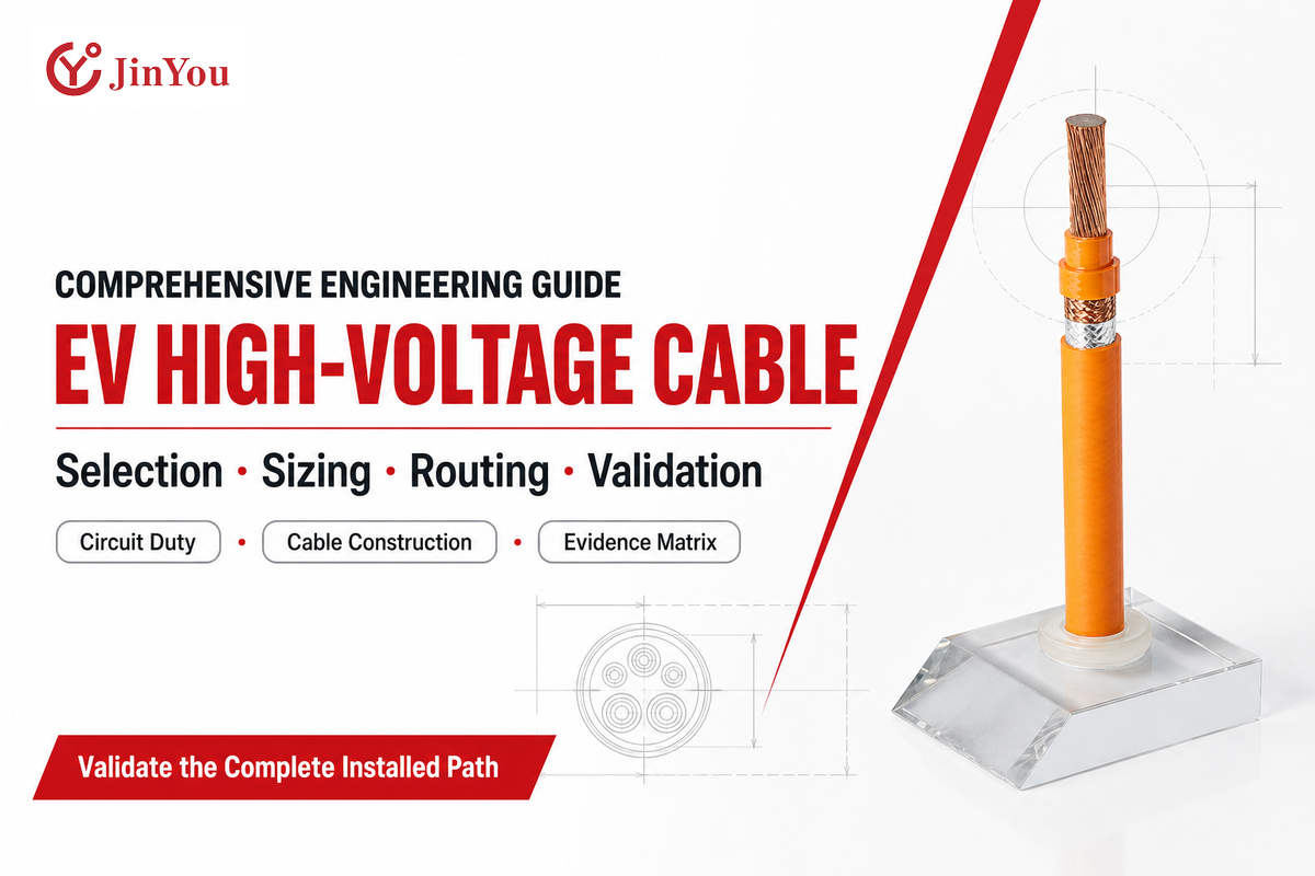
An EV high-voltage cable can’t be chosen based solely on the voltage, conductor size, or shield type. The cable is part of an electrical path connecting several high-voltage components within the vehicle including the traction battery, inverter, electric drive, on-board charger, DC-DC converter, etc. Each cable in the path must carry its share of the actual load while its insulation, cable jacket, shield, terminals, and route must continue to perform in the installed environment.
In this document, we’ll explain how an electrical circuit in a vehicle is converted into a brief that can be reviewed for a cable. In practical terms, we’ll explain how a vehicle circuit becomes a cable specification. This is different to a product description page. There are no universal Ampacity charts. There’s no recommendation of a model number. The publication of one standard reference will certainly not provide evidence that a cable will be approved to fit in a vehicle. The responsibility and acceptance of the final design, construction, and validation belong to the OEM’s qualified engineering team, the supplier, and the agreed validation plan.
Quick answer
An EV high-voltage cable should be selected based on several parameters rather than just the “800V” label, which defines one input only. These parameters are the complete circuit, maximum electric stress, continuous and peak currents, duty cycle, route, ambient and local temperatures, movement, exposure to fluids, terminal limits, EMC requirement, and project validation evidence.
| Input | Question to answer | Evidence to retain |
|---|---|---|
| Circuit | What components are connected, and what are the normal and abnormal voltage conditions? | Electrical architecture, interface definition, transient assumptions |
| Current | What are continuous, peak, duration, repetition, and allowed voltage-drop conditions? | Duty profile and thermal calculation inputs |
| Environment | Which ambient, local heat, fluids, contamination, and altitude conditions apply? | Zone map and material-compatibility requirements |
| Route | Where are the bends, clamps, movement, abrasion risks, and nearby heat or signal circuits? | Released routing study and installation drawing |
| Termination and EMC | Which terminals, shield architecture, noise sources, and grounding concept are defined? | Interface specification and EMC target |
| Acceptance | Which cable, assembly, and installed-system checks decide release? | Validation matrix, reports, deviations, and approvals |
1. What Is an EV High-Voltage Cable?
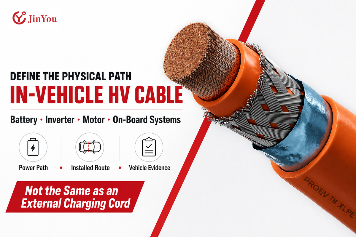
An EV high-voltage cable is a type of cable that carries power between high voltage components in a road vehicle. Common in-vehicle examples are circuits running from the battery to the inverter, the inverter to the motor, the battery to the on-board charger, and the battery to the DC-DC converter. The exact boundary of voltage is often context dependent, so “high voltage” should never be considered the same in different countries and regions.
An in-vehicle cable and an external EV charging cable aren’t synonymous. An in-vehicle cable is integrated in the in-vehicle wiring assembly and meets specific thermal, mechanical, electromagnetic, and assembly requirements. An external EV charging cable is part of the charging connection outside the vehicle or within the vehicle interface and may be subject to different product, installation, and test requirements. An online search for an EV cable mixes both definitions, which is why a project brief should specify the physical pathway prior to identifying a cable family.
The public scope of ISO 19642-1:2023 places its vocabulary and design guidance within road-vehicle cable applications. That scope is useful for terminology, but treating it as evidence that a particular cable, cable assembly, or vehicle has passed a project requirement creates a verification gap.
2. The 800 V Label Is Not the Specification
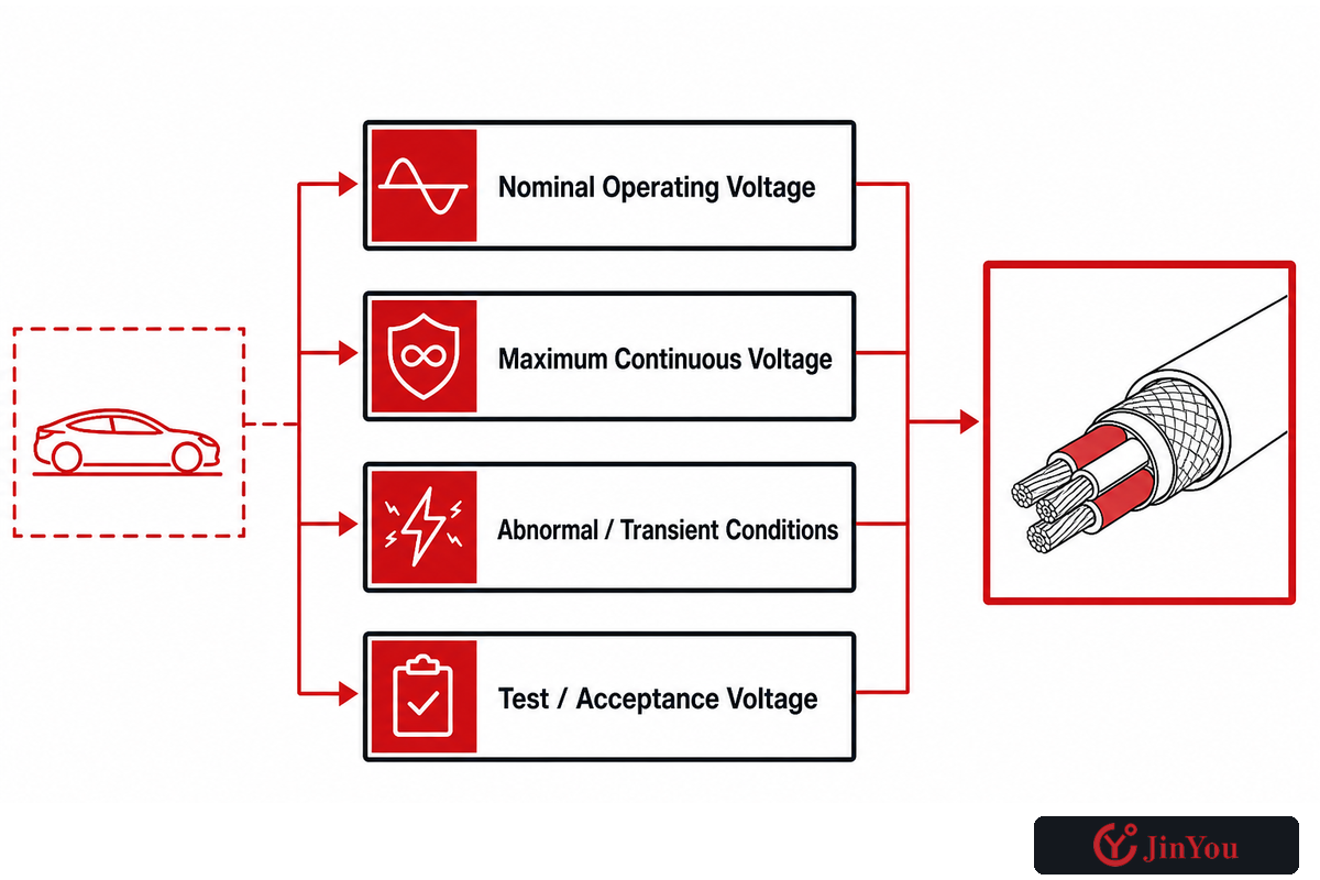
The term “800 V architecture” identifies a class of platform. “800 V architecture” helps identify a platform class, but it doesn’t tell an engineer the maximum continuous circuit voltage, transient envelope, switching conditions, or insulation margin required at a specific cable location. It doesn’t address the duration of the current, the temperatures of conductors and terminals, bundle derating, the length of the route, or the validation artifacts that an OEM expects.
Use a complete input form with at least four separate line items: nominal operating voltage, maximum continuous voltage, abnormal or transient conditions, and the project-defined test or acceptance voltage. These four items shouldn’t be consolidated to one line item. A battery DC path and an inverter-to-motor path can share a platform name, even though they can have very different current and electromagnetic conditions.
The 800 V label check
- What’s the maximum voltage the cable experiences during normal operation?
- What types of transients and switching phenomena does the design basis cover?
- What types of insulation and withstand evidence are required for the cable and final assembly?
- Who approves the final margin: the vehicle integrator, system owner, or another designated authority?
If those answers are missing, selecting a higher printed voltage rating may feel conservative, but it still doesn’t resolve temperature, packaging, terminal, or EMC risk. The next step wouldn’t be to guess a voltage based on the badge, but to complete the circuit definition.
3. Read the Cable as a Layered System
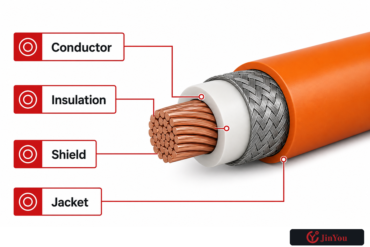
When looking at a cable data sheet, it’s more useful to relate each layer to both a function and an evidence question as opposed to thinking in terms of layers. For example, current carrying conductors are surrounded by dielectric insulation. Coupling between circuits may be controlled by a screen or shield. Finally, cable bedding, separators, fillers, tapes, and jackets provide shape and define the boundaries of layers. The final construction is protected by a jacket from damage caused by the environment where it’s installed.
| Layer | Primary job | What must be checked |
|---|---|---|
| Conductor | Carry the duty current with acceptable loss and temperature | Material, cross-section, stranding, current profile, resistance, terminal interface |
| Insulation | Withstand defined electrical and thermal stress | Material system, wall, voltage class, temperature class, aging and test evidence |
| Shield | Control coupling and provide the specified shield path | Construction, transfer-impedance target, coverage concept, termination and continuity |
| Jacket | Protect internal layers and provide identification | Abrasion, fluids, heat, flame behavior, marking, color and route exposure |
Layer names don’t prove performance. A thicker jacket, for example, may offer improvement for mechanical protection, however it could lead to increased stiffness and larger diameter. A defined cable shield material may improve performance while making cable construction harder. Compare the failure mode each layer addresses with the test or installed check used to verify that decision.
4. How Do Engineers Size an EV High-Voltage Cable?
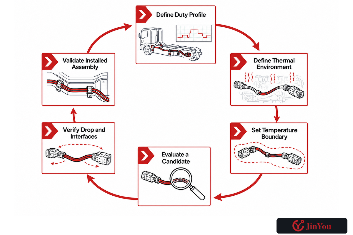
Engineers size an EV high-voltage cable by considering several factors including electrical duty, conductor temperature, voltage drop, terminal capability, and installation considerations. There’s no safe universally applicable table that can map 800 V or one current value to one cross-section. The same conductor is known to behave differently when it’s bundled, routed in the proximity of a heat source, enclosed, exposed to limited airflow, and connected to a terminal with a lower temperature boundary.
- Define the duty profile. Include the continuous current, peaks, duration, repetition, and regenerative operation. Include reasonably possible abnormal situations.
- Define the thermal environment. Distinguish between the general ambient and local heat zones, bundle and enclosure conditions, and heat conducted by components or terminals.
- Set the conductor-temperature boundary using the applicable cable construction, terminal system, vehicle requirement, and agreed design margin.
- Evaluate a candidate. Conductor resistance and loss calculations are required within the defined duty and installation assumptions.
- Verify voltage drop and interfaces. Confirm the result against route length, function of the circuit, terminal resistance, connector constraints, and system performance.
- Validate the installed assembly. Compare assumptions made during the calculation to measured temperature, voltage drop, and inspection evidence under true operating conditions.
This is a controlled calculation and not a lookup. A cross section may pass a conductor-temperature calculation and fail a terminal-temperature limit, packaging envelope, bend requirement, or voltage-drop criterion. Conversely, increasing the size of the conductor may add mass, diameter, stiffness, and difficulties of the termination without solving the true hot spot.
Keep assumptions prominent. If the current duration, ambient, bundle count, route length, or terminal data changes, the calculation must be reopened. That’s what it means to size by application rather than by specified rating.
5. Shielding Is an EMC System Decision
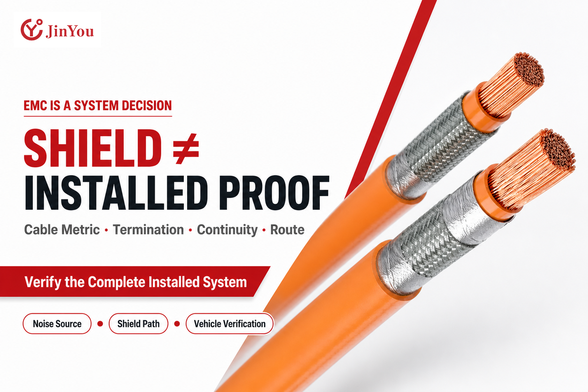
A shielded cable shouldn’t automatically be the right answer for every high-voltage path. The presence of a shield on a data sheet doesn’t mean the cable is shown to meet the installed EMC requirement. The first consideration is the noise source, frequency spectrum, circuits likely to be affected, route of the cable, emissions which are permitted, and possible flow of shield current.
Stable DC links can present a different EMC problem from inverter-to-motor cables driven by PWM. A route near sensors or communication wiring can also change the requirement. E-Mobility Engineering shows in its review of high-voltage cable designs how this application distinguishes itself: shielding needs depend on the circuit and its surroundings, not on voltage alone. Shielding isn’t so much a function of voltage as it’s of the overall circuit and its environment.
The shielding of a cable may be made using copper braids or foils, or a combination of both. The percentage of coverage is just one of the design parameters. Increasing the percentage of coverage may lead to greater stiffness and overall diameter, material, and cost with no promise of a better installed shield. Termination method, contact around the connector interface, continuity through the assembly, and the route in relation to the body of the vehicle may dominate the outcome in this case.
Evidence question
Please ask for the cable level shield metric, the assembly termination drawing, and the EMC verification performed on the installed system. These records are related, but none of these documents can be used to substantiate the others.
An OSTI-hosted transfer-impedance presentation defines transfer impedance as a measure of shield effectiveness. This is relevant cable evidence. This, however, can’t substitute for verifying the complete route and terminations at the vehicle level.
6. Routing and Environment Can Overrule the Datasheet
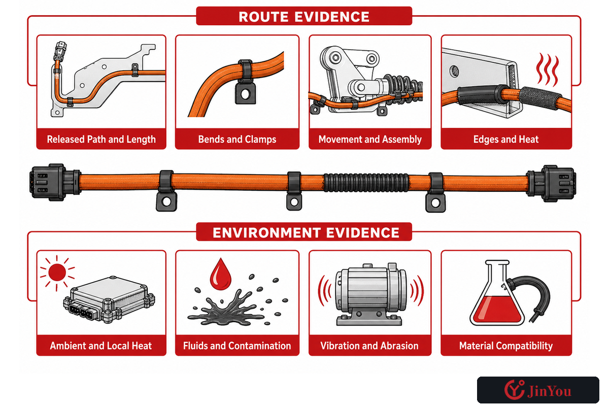
Even if a cable satisfies all its published construction requirements, it can still be unsuitable for a particular route. Bend geometry, clamp placement, vibration, edge contact, service movement, assembly sequence, local heat, splash zones, and fluid exposure can all change the stress on insulation, shield, and jacket.
Create a route-zone map before approving construction. Include heat sources, moving interfaces, clip and clamp locations, pass-throughs, potential abrasion points, water or chemical exposure, and proximity to sensitive circuits. Connect each zone to a material requirement and a verification method. “Engine compartment” is too generic if one segment is next to a heat source and another is in a protected guide.
Route evidence
- Released path and cable length
- Bend and clamp locations
- Movement and assembly sequence
- Clearance from edges and heat
Environment evidence
- Ambient and local temperature
- Fluid and contamination zones
- Vibration and abrasion exposure
- Material compatibility requirements
Importing a minimum bend radius or clamp spacing from an unrelated cable shouldn’t be done. Static installation, repeated movement, assembly handling, and service access are all distinctly different conditions. Use the exact construction data, wiring assembly drawing, installation instruction, and vehicle-program criteria that apply to the route.
7. Which Standards Apply to an EV High-Voltage Cable?
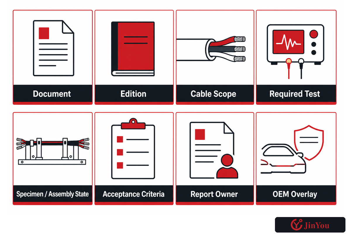
Standards should be read as a scope map, not a badge. ISO 19642-1:2023 supplies vocabulary and design guidance for the ISO 19642 road-vehicle cable series. The public scope of ISO 19642-9:2019 addresses round, sheathed, screened or unscreened multi- or single-core copper conductor cables in stated voltage classes, including 600 V AC/900 V DC and 1000 V AC/1500 V DC.
This doesn’t mean that every cable sold with that voltage is automatically in that construction part. A reference to the standard doesn’t ensure compliance by the supplier. The applicable part depends on the conductor material, core arrangement, screening, sheathing, voltage class, edition, and the invoked requirements. The detailed clauses also remain subject to the licensed standard and the purchaser’s specification.
UL Solutions’ automotive cable testing overview is helpful because it separates thermal, environmental, flame, mechanical, chemical, and electrical characteristics. Those categories can guide a validation matrix, but they aren’t proof that a specific cable carries a UL mark or has passed a named program.
The final standards list should include the document, edition, scope of cable, required test, state of the specimen or assembly, acceptance criteria, name of the report owner, and any OEM overlay. Do not use the phrase “ISO certified vehicle cable” unless supportive evidence clearly indicates this statement.
8. Build a Validation Matrix Before Approval
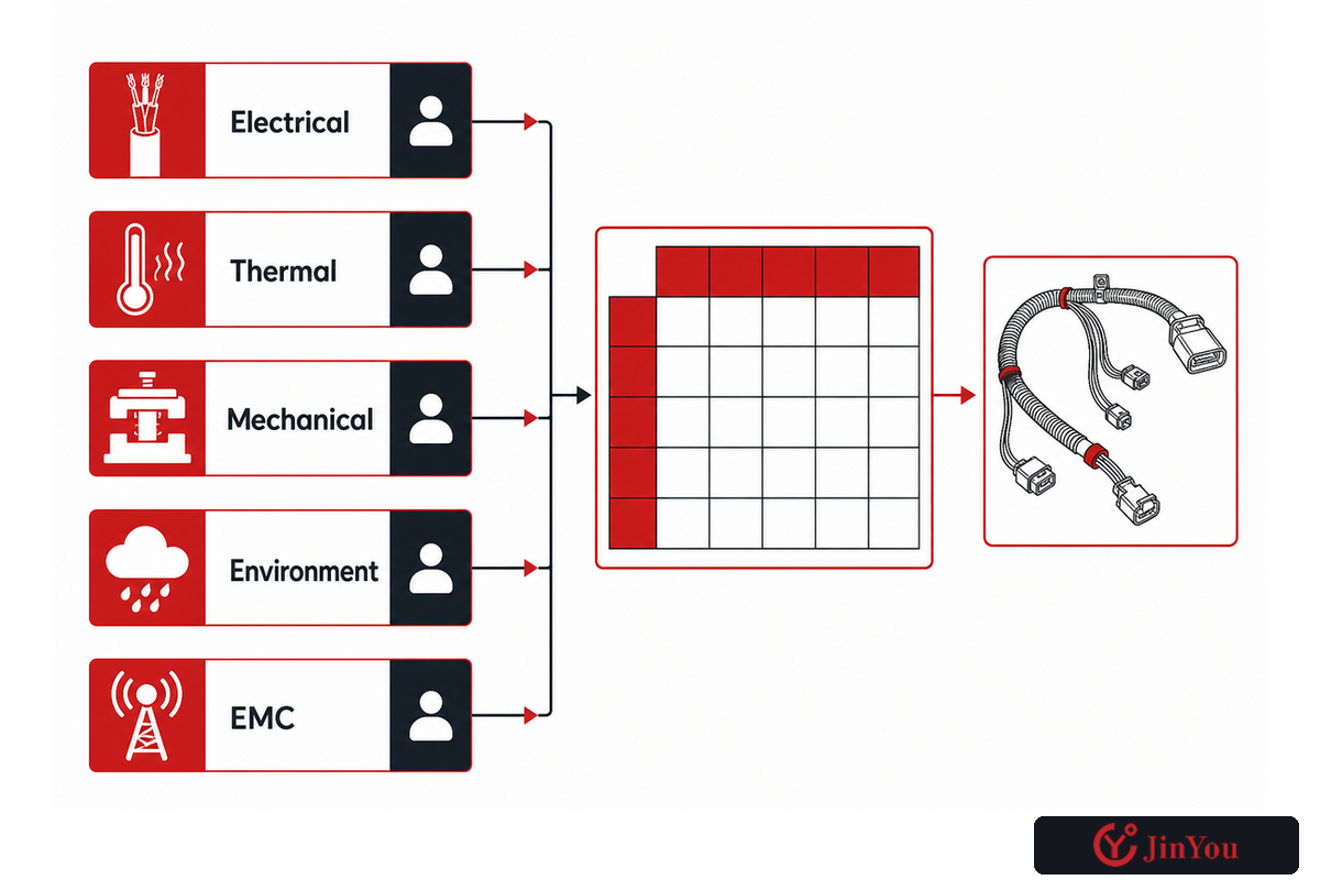
A validation matrix transforms broad quality language into decisions (rules). Each row consists of a risk, the entity being tested, the condition, the acceptance rule, and the evidence owner. This is important because a cable specimen, a terminated cable assembly, a routed cable assembly, and a complete vehicle answer different questions.
| Domain | Object | Evidence question | Typical owner |
|---|---|---|---|
| Electrical | Cable and assembly | Are resistance, voltage drop, insulation resistance, and withstand results within the agreed criteria? | Cable supplier and system owner |
| Thermal | Installed path and terminals | Do measured temperatures support the calculation under representative duty? | Vehicle integrator |
| Mechanical | Cable, assembly, route | Does the construction tolerate the defined bend, vibration, abrasion, retention, and handling? | Supplier and wiring integrator |
| Environment | Materials and sealed interfaces | Are heat, fluids, moisture, contamination, and aging conditions represented? | Materials and validation teams |
| EMC | Cable, terminations, installed system | Are the cable-level target, shield continuity, route, and vehicle result all verified? | EMC and system teams |
There should be fields for samples, revisions, pre-conditioning, test ordering, instrumentation, pass/fail criteria, retest criteria, and record retention in the matrix. If a requirement changes after testing, the matrix shows which rows need to be reopened instead of assuming the whole result remains valid.
Publishing a voltage class, size range, material, or construction on a first-party product page is helpful to candidate selection. They aren’t matrix inputs or evidence of compatibility with a vehicle route that the supplier hasn’t reviewed.
9. Diagnose the Failure Mode Before Replacing the Cable
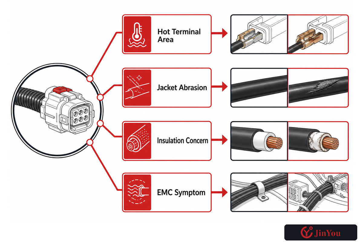
“The HV cable failed” isn’t a good starting theory. Hot terminals, warm conductors, abraded jackets, insulation test concerns, and EMC symptoms are indicators of different types of evidence. Replacing the cable in the presence of those different types of evidence can either recreate the same issue, or mask an interface problem.
| Observed symptom | Next evidence to compare | Avoid assuming |
|---|---|---|
| Hot terminal area | Current profile, joint resistance, crimp/process record, contact condition, thermal image | That conductor cross-section is the only cause |
| Jacket abrasion | Route drawing, clamp and edge contact, movement marks, installation history | That insulation material alone is defective |
| Insulation concern | Approved electrical test, contamination, moisture, damage, aging and event history | That appearance proves dielectric condition |
| EMC symptom | Noise source, operating state, shield continuity, termination, route and nearby circuits | That adding braid coverage will fix the vehicle |
This is a routing tool for a qualified investigation. High-voltage systems require the applicable isolation, de-energization, service, and authorization controls. Preserving the failed state and its evidence is important before changing multiple variables. A clean comparison between the drawing and the build record, the measured vs. designed values, and the operating condition is of more value compared to a quick parts swap.
10. Use the Evidence Owner Matrix Before Requesting a Cable
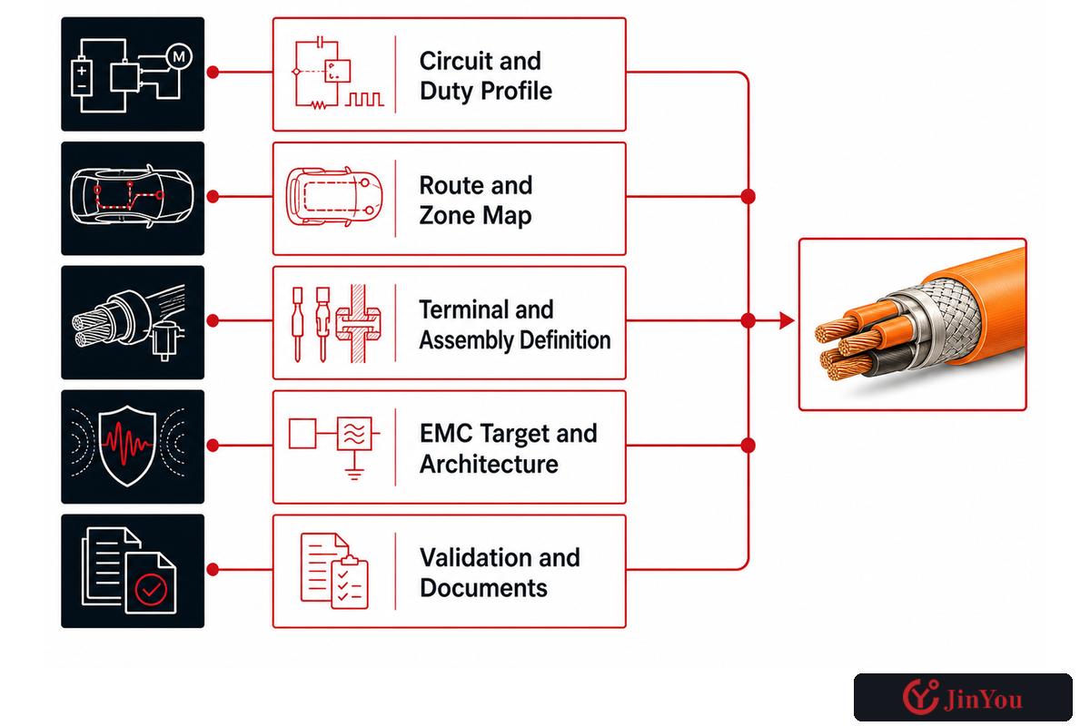
The evidence owner matrix is the handoff from vehicle engineering to a cable supplier. The matrix prevents the request from being made as “please quote orange 800 V shielded cable.” Rather, each input has an owner, revision, and a decision that it supports.
| Evidence package | Owner | Supplier decision enabled |
|---|---|---|
| Circuit and duty profile | System engineering | Voltage class and conductor candidate |
| Route and zone map | Packaging and wiring teams | Diameter, flexibility, jacket and installation review |
| Terminal and assembly definition | Electrical integration | Stranding, interface and process review |
| EMC target and architecture | EMC engineering | Shield candidate and termination inputs |
| Validation and documents | Program quality/validation | Sample, test, report and approval plan |
Once complete, it’s appropriate to direct project teams toward the existing EV high-voltage cable solution page. This page is the next step in the commercialization process for published construction options and project inquiries. This page is the engineering preparation layer and isn’t a duplicate of the product page, which is intended for the sales function.
Have a circuit brief ready for review?
Please provide the load profile, route, environment, termination, EMC consideration, and the evidence required. JINYOU will evaluate the construction options available based on the information provided.
EV High-Voltage Cable FAQ
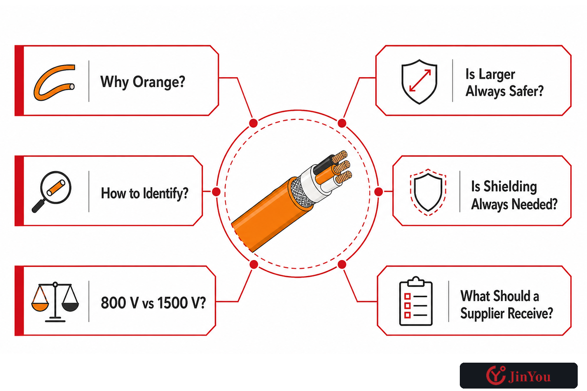
Why are high-voltage cables orange in electric vehicles?
In many vehicle systems, orange makes a high-voltage circuit identifiable. It aids a user in distinguishing a high-voltage wiring assembly from a low-voltage wiring assembly. Color alone doesn’t identify voltage class, isolation, construction, or safe working conditions. The required identification and markings depend on the vehicle program and the region to which the vehicle is destined. In the absence of a vehicle program and a service procedure, don’t assume that an orange-covered wiring assembly is a complete technical identification.
How can you identify a high-voltage cable in an EV?
Start with the released electrical architecture of the vehicle, wiring assembly drawing and labels, interface connectors, and service information. Orange is a frequently used identification, but isn’t a complete high-voltage identification system. A high-voltage path should remain traceable to its circuit, component interfaces, cable part number, and applicable warnings. Don’t probe or handle a suspected high-voltage cable based on appearance; follow the authorized isolation and service procedure for that vehicle.
Is every 800 V EV cable rated for 1500 V DC?
No. An 800 V platform name and a 1500 V DC cable-class reference describe different things. The cable requirement depends on maximum operating conditions, transients, construction scope, temperature, terminals, route, and the project’s standards and acceptance criteria. ISO 19642-9 publicly includes a 1000 V AC/1500 V DC class within its stated cable scope, but that does not make every 800 V vehicle cable a Part 9 construction or prove that any candidate is accepted.
Does a larger conductor always make an EV high-voltage cable safer?
No. Increasing the conductor size can decrease resistance and reduce overall heating; however, it changes mass, diameter, flexibility, and bend behavior. There are also changes to the packaging of the cable and the terminals. The hottest point can be a connection rather than the cable span. Therefore, engineers consider the assembly, validation, and thermal conditions in conjunction with the duty and voltage drop. “Going larger” shouldn’t be a substitute for finding the limit.
Does every EV high-voltage cable need a shield?
There’s no one rule that can be applied to each and every circuit. Shielding is also dependent on the noise source, the behavior of the switch, the nearby sensitive circuits, the allowed emissions, and the termination of the cable. A stable DC segment may present a different challenge from an inverter-to-motor path. Where shielding is required, construction of the cable, transfer impedance, assembly continuity, termination, routing, and installed EMC should be treated as separate but connected elements of the evidence.
What should be sent to an EV cable supplier for review?
Send circuit, maximum voltage, continuous and peak current, route length, ambient and local temperatures, bundle and enclosure conditions, bend and movement requirements, exposure to fluids, terminal system, EMC target, related standards, validation matrix, and documentation. Open assumptions need to be marked. A supplier can review a construction more reliably when the request explains the application and evidence needed instead of listing only voltage, current, and color.
References and Evidence Boundaries
- ISO 19642-1:2023 public vocabulary and design-guideline scope for road-vehicle cable applications.
- ISO 19642-9:2019 public scope for specified sheathed, screened or unscreened copper cable constructions and voltage classes.
- UL Solutions automotive cable testing overview independent summary of thermal, environmental, flame, mechanical, chemical, and electrical evaluation domains.
- Transfer Impedance technical presentation measurement of cable shield; doesn’t address vehicle level EMC approval.
- E-Mobility Engineering: Cables trade engineering discussion of insulation and shielding, cable routing, and system integration.
Editorial boundary: Public standard pages describe document scope; they don’t certify a product. JINYOU’s published product information is first-party information and is still within the constraints of the project specification and evidence review. This article provides an engineering decision framework. This article doesn’t give design approval for a vehicle, provide a service instruction, or substitute for qualified high-voltage safety procedures.
Context by the publisher is available on the JINYOU About Us page.