Get in touch with JINYOU Cable Company


Guide at a glance
Application: stationary battery energy storage. Circuits: DC power, AC power, signals and auxiliaries. Selection basis: Electrical duty, installed conditions and compatible interfaces. Scope: technical information, with an illustrative loss calculation.
Energy Storage Cables carry power or signals between battery-system components. A thick conductor can still be the wrong choice if its terminal, installation category or operating conditions don’t fit the circuit. Start with the connection’s purpose, then assess the complete path.
Updated October 2026 · Author: GW
Energy storage cables connect power, control and monitoring circuits in a battery energy storage system. Suitability depends on the circuit, installation and complete termination system. A voltage rating alone does not establish current capacity or permitted use.
Key takeaways
- Component-wire recognition does not automatically establish field-installation suitability.
- Doubling current produces four times the resistive loss when resistance stays fixed.
- Connector conditions and fault protection belong beside conductor sizing.
- System certification and fire-test reports answer different questions from cable approval.
Energy Storage Cables: Function and System Boundaries
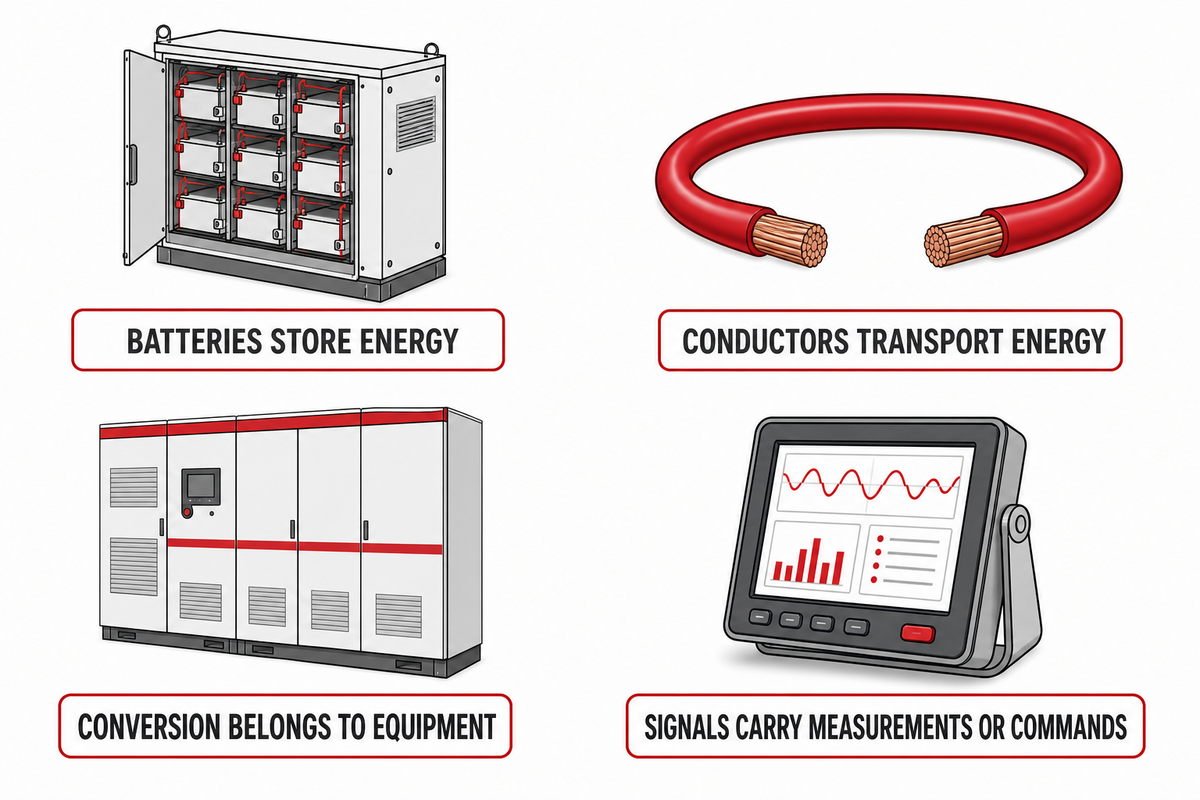
Cables used in energy storage systems provide electrical paths within the equipment and between its separate units. The battery holds energy; conductors transport electrical energy, while signal circuits carry measurements or commands. The same project therefore needs several cable functions, each with its own electrical and mechanical requirements.
A battery installation can support renewable energy, backup power or load shifting. Its ability to store energy comes from the storage technology and equipment, not from the cable insulation. Likewise, a conductor doesn’t convert DC electricity to AC power. In the 2021 Energy Storage Handbook chapter on power conversion systems, Sandia assigns conversion and control to the relevant equipment.
For a BESS project, map the energy transmission paths between storage and distribution equipment and identify each signal connection. The term “battery cable” leaves a lot unanswered; a rack output, a voltage-sensing lead and a cabinet aux. supply have distinct functions.
DC, AC and Communication Cables in a BESS
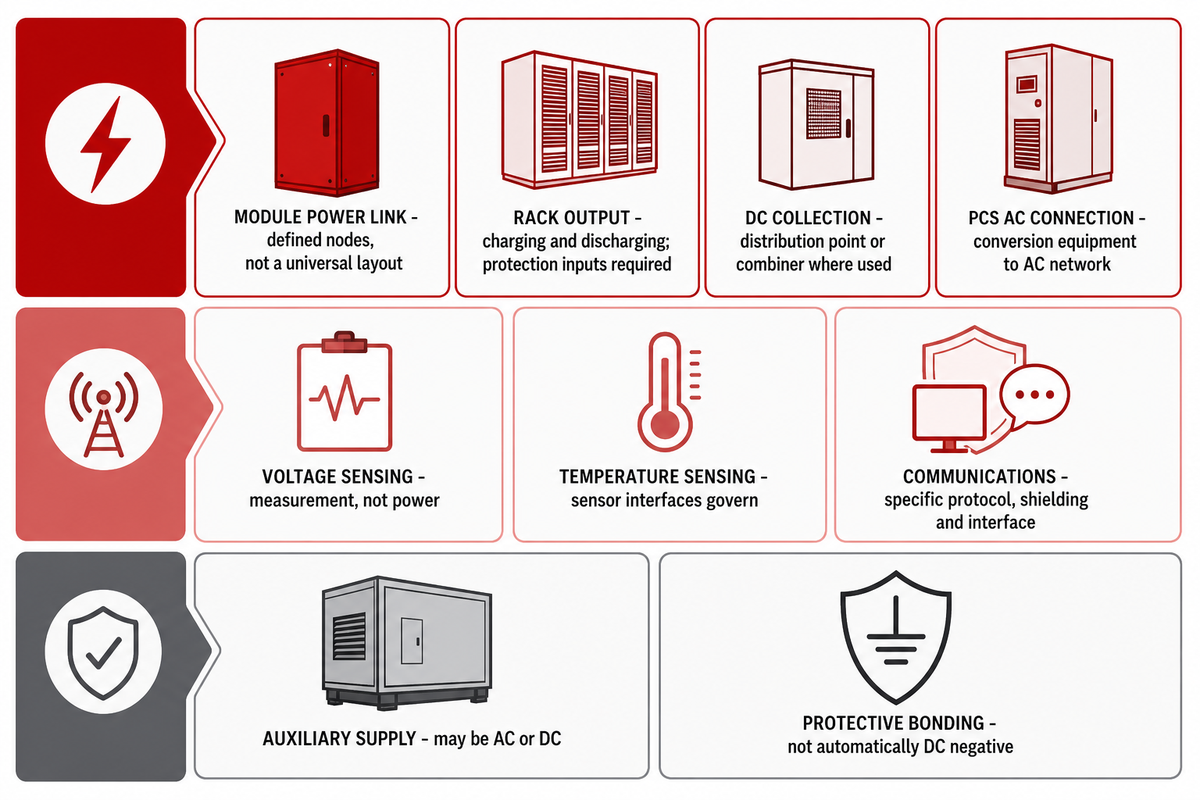
DC power cables carry direct current on the battery side of conversion equipment, while AC power cables carry alternating current where architecture dictates. Their functions vary; monitoring, communications and auxiliary circuits are distinct. Protective bonding must have a defined path, and isn’t interchangeable with a return path.
| Connection | Function | Limitations / Not suitable for |
|---|---|---|
| Module power link | Transfers battery power between defined nodes | Not a universal connection layout |
| Rack output | Carries charging and discharging current | Requires rack and protection design inputs |
| DC collection link | Connects a distribution point or combiner where used | Not every system uses a separate combiner |
| PCS AC connection | Connects conversion equipment to the AC network | DC product suitability cannot be assumed |
| Voltage sensing | Carries measurement information | Not a substitute for a power conductor |
| Temperature sensing | Connects sensors and monitoring electronics | Sensor and interface requirements govern |
| Communications | Exchanges data between management systems | Protocol, shielding and interface are specific |
| Auxiliary supply | Powers specified controls, fans or other loads | May be AC or DC; check the equipment |
| Protective bonding | Provides the designed protective connection | Not automatically the DC negative conductor |
What is PCS in a BESS project?
A power conversion system, or PCS, includes inverter functions to connect batteries and the grid in an AC-connected system. Its functions vary with architecture including the presence of separate DC conversion stages. Cables connect these system components; their ratings must match the actual interfaces rather than a generic PCS diagram.
Power transmission through the DC side and connection to power grids are different duties. The OSHA wiring-design requirements also distinguish grounding arrangements and require an effective grounding path. The designer must establish those arrangements; a simplified diagram can’t decide which battery pole, if any, is earthed.
Why are communication cables important for energy storage systems?
The communication cables carry data needed for coordinated monitoring and control between the battery management system, conversion equipment and supervisory controls. Their interface requirements differ from those of power conductors. A battery management system may also have separate sensing and auxiliary connections, so a data cable cannot replace every BMS connection.
Use the connection map and routing instructions for the equipment. An incomplete or incorrect interface may result in an incomplete energy flow, regardless of the adequacy of the primary conductors’ cross-section. The cables that connect controls warrant the same type of drawing and identification as the power path.
Conductors, Insulation and Flexibility
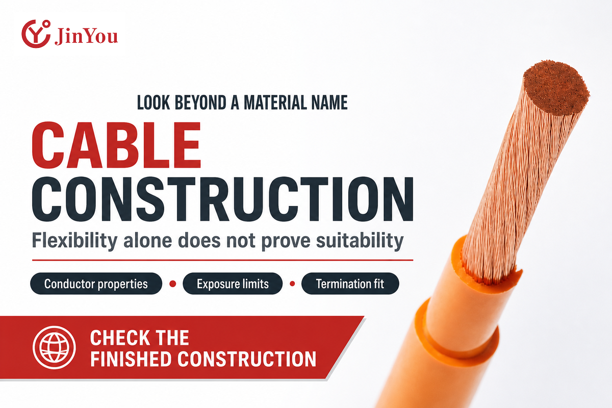
The properties of the conductor material and the conductor cross-section affect the conductor’s resistance. The construction of the strands affects handling and termination fit. Insulation and sheath properties govern different exposure limits. Comparing properties of the different layers of cables used in energy storage is more useful than considering “flexible” or a polymer name as a complete specification.
For cables used in battery equipment, conductivity alone does not settle size and weight, terminal compatibility or the available bend envelope. A fine-strand conductor still needs a proper end termination. UL’s June 2011 fine-strand termination explanation describes conductor-class identification. That historical discussion explains the compatibility issue. It isn’t a claim about the code edition adopted for a current project.
There are test conditions associated with materials comparisons as well. A 2018 polyethylene-blend study compared electrical and mechanical behavior at specified temperatures. A different XLPE aging study looked at the effects of water and an aqueous copper sulfate solution. Both studies focused on specimens from the lab. Neither supplies a finished BESS cable’s service life, current rating or permission for immersion.
Ask what the finished construction has been evaluated to withstand. Questions regarding halogen content, flaming behavior, wet exposure, and repeated movement are other questions. Easy bending during assembly doesn’t, by itself, prove suitability for repeated flexing in service.
Sizing Energy Storage Cables: Thermal Limits and Voltage Drop
Cable sizing needs an installed thermal assessment, an acceptable voltage drop and compatible protection, as well as suitable terminations. A resistance calculation explains one part of energy loss. It cannot establish the continuous current allowed in a tray, conduit or cabinet, or the assembly’s performance during a fault.
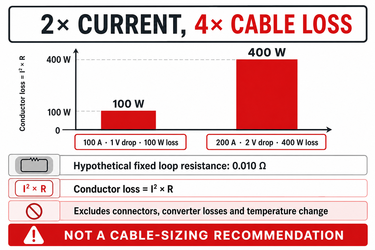
For a resistive DC loop, use voltage drop = I × R and conductor loss = I² × R. Here, I is in amperes and R is the total outgoing-and-return conductor resistance in ohms at the assumed temperature. Contact resistance also contributes to loss.
2× Current, 4× Cable Loss
Consider a hypothetical cabinet connection with a complete conductor-loop resistance of 0.010 Ω. At 100 A, the voltage drop is 100 × 0.010 = 1 V, and conductor loss is 100² × 0.010 = 100 W. At 200 A, the same assumed loop drops 2 V and dissipates 400 W. The arithmetic explains why a modest-looking current change can matter to heat removal. It doesn’t identify a suitable conductor size. The example holds resistance fixed, excludes connectors and converter losses, and makes no allowance for changing conductor temperature. An engineer would still check the actual cable construction, route, ambient conditions and protection before accepting either operating point.
| Current | Voltage drop | Conductor loss |
|---|---|---|
| 100 A | 1 V | 100 W |
| 200 A | 2 V | 400 W |
At a two-hour, assumed steady operating state, those losses would be 0.2 kWh and 0.8 kWh, respectively. This compares conductor heat over time; it does not represent total system energy efficiency or a project’s annual bill. Load profiles, temperature, and other factors would need to be considered for an actual assessment.
Another consideration is fault duty. For feeders and branch circuits over 600 V nominal, OSHA 1910.304(f)(2)(iii) explicitly coordinates available short-circuit current, protective-device operating time and conductor heating. The lower voltage provisions of the standard, and other provisions, have a different scope. For protective limitations, you would need to rely on applicable engineering, not the steady-state loss table.
The useful output is a set of compatible limits: cable, terminal, connector, installation and fault protection. Choosing the right cable means resolving all of them rather than passing whichever calculation is easiest.
Connectors, Terminations and Parallel Paths
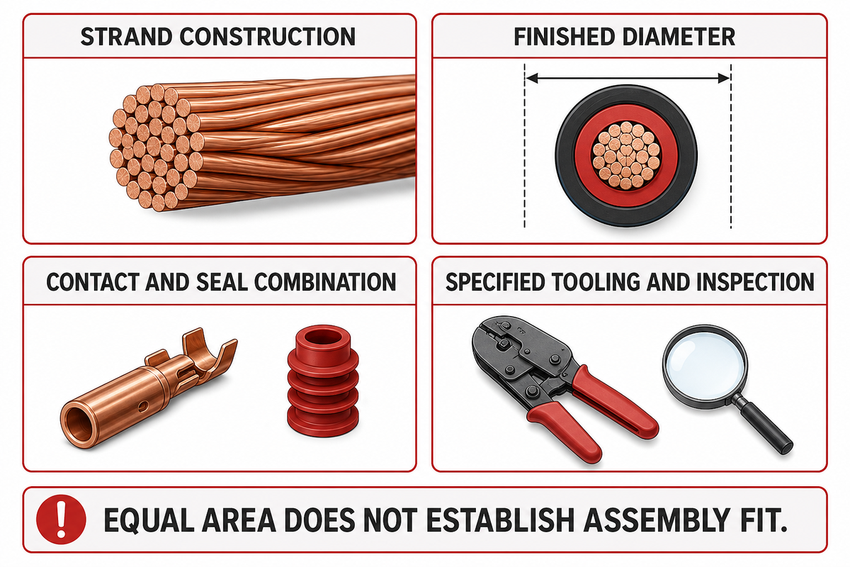
Connectors and terminations can limit an otherwise suitable conductor. Current ratings belong to defined contacts, cable combinations and thermal conditions; mechanical fit alone does not establish electrical suitability. Parallel battery paths also need a whole-path assessment, including connections, as opposed to a comparison of cable alone.
For example, the product page for Stäubli’s BCC-Evo lists figures for 1,500 V DC, 250, 300 or 350 A, with a temperature rise of less than 45 K. These are Stäubli’s conditional product figures. Not Jinyou ratings or a general BESS cable table. A listed voltage and current value answer different questions.
In a hypothetical cabinet redesign, a purchasing team keeps the same conductor area but chooses a more flexible construction. The new cable bends neatly, yet its strand construction and finished diameter differ from the connector’s approved range. The assembly can’t be accepted from area alone. Engineering checks the contact and seal combination; production checks the specified tooling and inspection method. A more flexible cable may be cheaper, but that may be outweighed by the cost of a connector change and/or reworking the assembly; that cost needs a real quotation. The decision is whether the entire assembly fits the design.
For parallel battery systems, consider the whole outgoing-and-return path under the manufacturer’s topology. Poor connections can undermine length-only assessments. Where several interfaces form a controlled assembly, energy storage wiring harnesses provide separate drawings and assembly scopes.
Cable Standards, System Certification and Test Reports
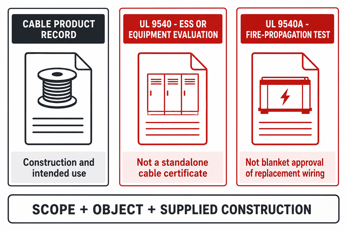
Evidence of cable describes a specific product and a particular intended use. System evidence considers a larger assembly or a defined test. A standard number is the starting point for the distinction. Consider the scope of the document, the object covered and the construction being supplied before interpreting two records as similar.
The UL wire and cable guide explains that component wiring generally hasn’t been evaluated for field installation unless it’s part of a complete Listed product or system. UL 758 and an Appliance Wiring Material style designation therefore need their equipment-use context. A printed style number does not automatically mean wire can be installed anywhere.
| Evidence or proposed change | Question it helps answer | Limitations / Not suitable for |
|---|---|---|
| Cable product record | Which construction and use are covered? | Does not size every installed circuit |
| AWM style designation | Which component-wire construction is identified? | Not unrestricted field-wiring approval |
| UL 9540 evaluation | Which ESS or equipment assembly is evaluated? | Not a standalone cable certificate |
| UL 9540A report | What happened in the specified fire-propagation test? | Not blanket approval of replacement wiring |
| IEC 62933-5-2 scope | How is electrochemical ESS safety addressed as a system? | Does not select a cable model for the buyer |
| Connector datasheet | Which interface and rated conditions apply? | A 1,500 V label does not define amperage |
| Equal conductor area | Is nominal metal cross-section comparable? | Does not establish strand or terminal fit |
| PV cable substitution | Can that exact construction meet the proposed duty? | Solar labeling alone cannot answer |
| Busbar substitution | Can the rigid connection meet the assembly design? | Requires interface, spacing and mechanical review |
UL’s ESS certification description and its UL 9540A test-method description cover different evidence. The former addresses system and equipment safety; the latter concerns thermal-runaway fire propagation. Neither turns an unrelated cable into an approved substitute.
The public scope of IEC 62933-5-2:2025 addresses grid-connected electrochemical storage across its life cycle, including interactions between subsystems. Industry standards remain within their scope and the project’s applicable edition.
In this solar cable documentation example, the photovoltaic context shouldn’t be mistaken for proof of energy storage cable certification.
PV Cable, Battery Cable and Busbars: When Substitution Fails
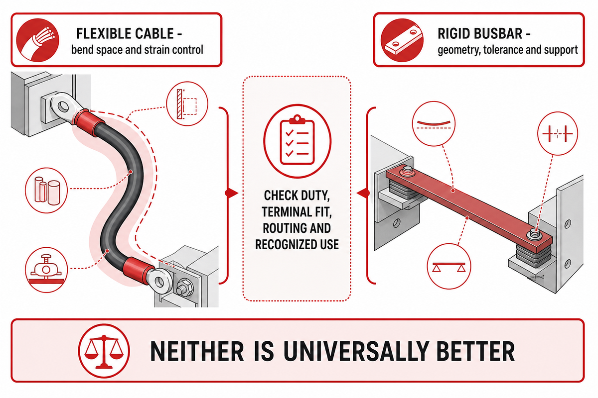
Whether a cable is suitable as a replacement depends on the application, rather than agreement among a few label values. A given cable may carry the required voltage, but be an unsuitable replacement because of terminal fit, routing, or recognized use. The design of the electrical and mechanical system of the equipment may allow a rigid conductor to replace a flexible connection.
A photovoltaic power cable belongs to a solar power application family. An electric vehicle cable belongs to another equipment context. Either description is too broad to prove or disprove suitability for every stationary battery circuit. The candidate’s actual records must resolve that question.
For busbars, compare the connection geometry as well as current. A rigid link changes assembly tolerances, service access and mechanical support. A flexible cable accommodates a different layout, but it still needs bend space and strain control. Neither construction has a clear advantage for all battery energy storage applications.
OSHA 1910.303 takes into account bending space, suitability of installation, heating and the equipment’s identified use. These are reasonable limitations to assess the proposed change as an assembly. The useful comparison is the cable’s ability to withstand the specified duty, not the broadest marketing claim.
Cable Management and Failure Prevention
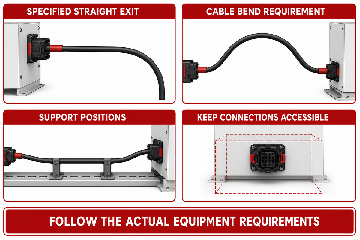
Cable management should protect insulation, support connections, and preserve thermal and service conditions. Routing decisions affect cable behavior through bend geometry, mechanical strain and heat removal. An easier assembly route may not be easily inspectable or suitable for the specified environment.
“Space and flexibility are key in BESS.”
Common failure modes to catch before release
Imagine a compact battery cabinet, whose power leads meet the planned length. Connectors are located close to a panel and the cable must turn immediately after that. Worsening bend and terminal loads could occur with a larger conductor. The review therefore includes the connector’s specified straight exit, cable bend requirement and support positions before the enclosure is frozen. No failures are assumed; the idea is to identify conflicts while changes can still be made to drawings. Installation and maintenance access are part of that decision because a connection hidden behind a tight bundle is harder to examine or replace.
Points for review include abrasion at entries, unsupported masses at terminals and contact combinations outside the manufacturer’s guidelines. Review the equipment’s specified power and signal routing and shielding. Separation distances from unrelated installation types shouldn’t be applied universally.
Routes outside the building should be reviewed for exposure to moisture, sun and chemicals. A cable tray indicates a route and doesn’t assume environmental suitability. Extreme environmental conditions need evidence for the actual exposure, rather than an unqualified “outdoor” claim. These checks, at best, support long-term reliability, without assuming that visual inspection would prove the condition of the electrical lines.
Comparing Specifications Before Procurement
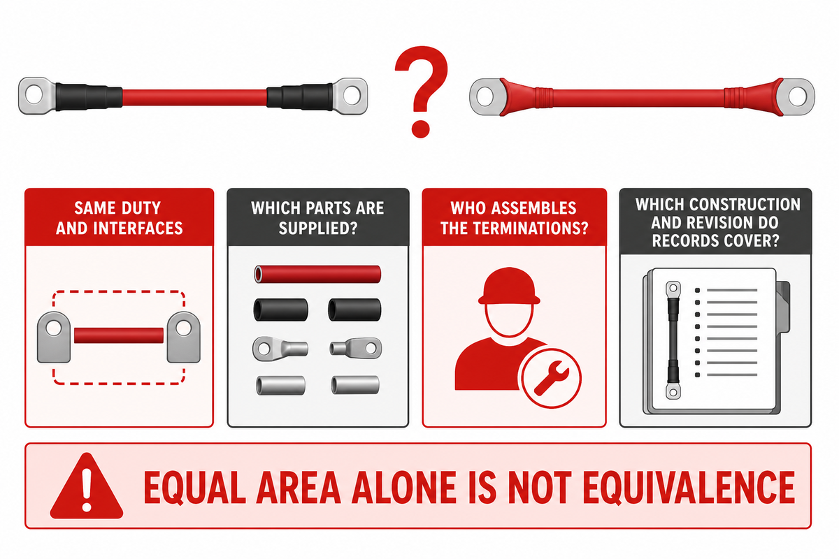
An equal sized conductor doesn’t guarantee equal assembled performance or scope of supply. A useful commercial comparison holds the duty and interfaces constant, then identifies differences in supplied parts, assembly responsibility and supporting evidence. A lower price can’t offset a cable solution that doesn’t fit the design.
From an engineering standpoint, the issue is whether the combination meets the installed conditions. For quality staff, it is whether the exact construction and revision match the records. For procurement, different mating parts or a different scope of termination can make two prices incomparable. Claimed lower installation costs need a defined assembly method and actual project quantities.
Once the circuit and evidence boundaries are clear, review Jinyou’s energy storage cable solutions for project-specific configuration and technical support. Operating requirements, reliable power, thermal limits and service access must remain with the discussion.
What Recent Safety Updates Mean for Cable Decisions
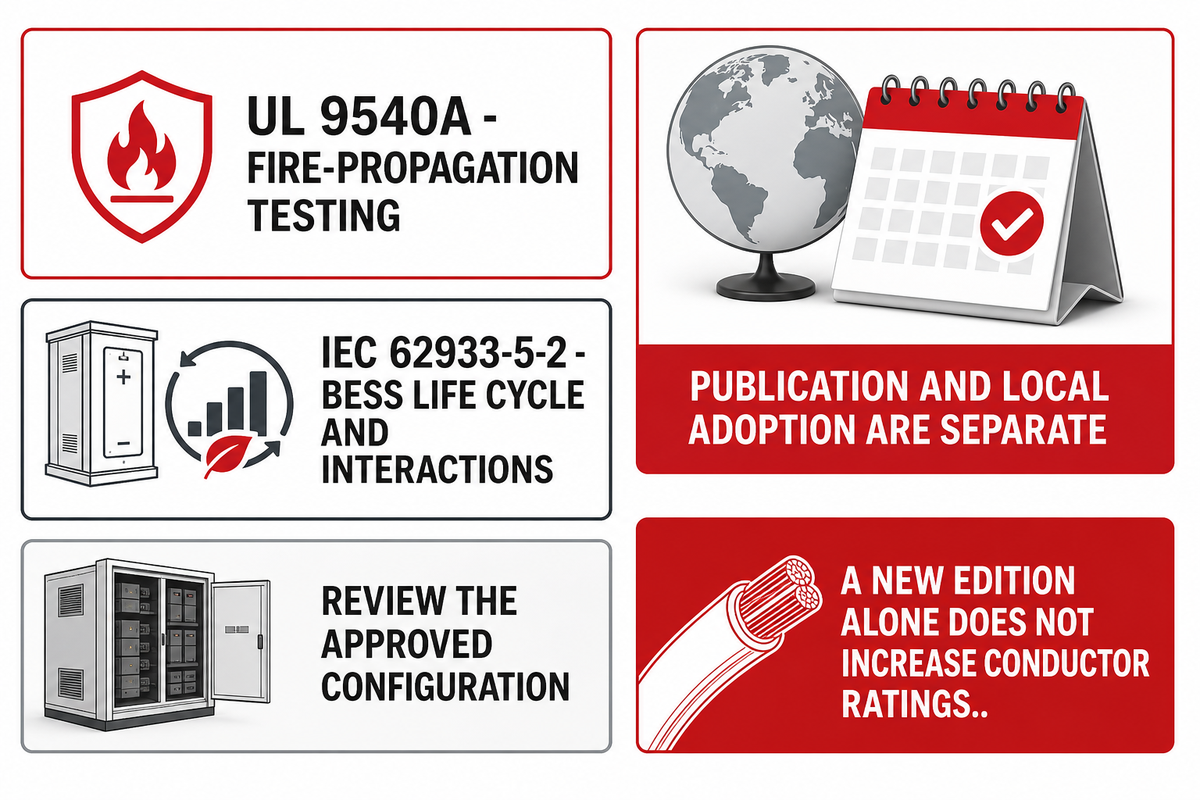
Recent system-safety updates make the tested configuration and document edition more relevant to cable decisions. A new edition does not increase an existing conductor’s rating. It’s important to determine what requirements and what equipment records govern a project, and assess proposed changes against that.
UL’s installation-code FAQ dates the sixth edition of UL 9540A to March 13, 2026. It covers system fire-propagation testing. A buyer reviewing a new report should establish the tested equipment and report edition before assuming that its findings cover a different cable arrangement. Publication and local adoption are separate events.
IEC’s public page gives December 9, 2025 as the publication date of IEC 62933-5-2 edition 2. The scope addresses the BESS life cycle and interactions between subsystems. For energy systems assembled from several suppliers’ equipment, that scope is a reason to keep cable design and interface changes connected to the system review. It is not a substitute for analyzing the applicable requirements.
Deployment growth provides context. In August 2026, the U.S. Energy Information Administration reported 43.6 GW of utility-scale battery power capacity at the end of 2025 and 8.3 GW added in the first half of 2026, bringing the total to nearly 52 GW. These are power capacity figures and not stored energy figures or growth rates of cables measured over that time.
Projects incorporating wind and solar with storage must route energy transfer through equipment with various functions. Renewable energy sources can change the timing of supply and demand; cable selection still follows the resulting electrical duty. An ability to deliver power on demand or serve times of peak demand depends on the full system and its controls. No cable choice alone determines these results.
For a new project or replacement, record the approved configuration before comparing alternative energy storage solutions. Preserve the circuit purpose, interface references and applicable edition when a part changes. That makes the next review specific enough to find a mismatch.
Frequently Asked Questions
Can energy storage cables be reused or recycled?
Cable reuse requires an application-specific condition review; recycling is a separate material-recovery decision.
While previous service, condition and identification of a part can provide valuable information, appearance alone can’t determine the electrical condition of a part. The equipment owner, together with qualified personnel, must establish if a part may be reused and what further testing is required. Material recovery depends on the cable construction and the recycler’s accepted process. Reusable conductor and recyclable material aren’t the same.
When should BESS cable management be planned?
Cable management should be planned before cabinet layout and interface positions are fixed.
Reserve the required bend space, support points, and service access, as shown in the equipment layout. Determine how the selected route impacts installation conditions and access to connections. Both a large battery installation and a compact cabinet require a route, based on their actual equipment instructions, and have different space constraints. Late changes can move the conflict from the cable to its terminal.
Can BESS cables be installed above ground?
Aboveground installation is possible when the specified cable, support and route meet the project’s requirements.
There are site-specific factors such as sunlight exposure, moisture, mechanical damage, and environmental conditions, which need to be considered for the actual location. Protective and supporting measures must be in accordance with the approved design and product instructions. A family name does not establish every exposure rating, and an aboveground route isn’t automatically preferable to a buried route. Compare installation conditions and access and the maintenance plan before the project team selects the route.
Does a 1,500 V rating specify the current a cable can carry?
A 1,500 V rating describes a voltage limit, not an ampacity value.
Allowable current also depends on the conductor, temperature, installation and terminations. The complete assembly may be limited by a connector even when the voltage rating of the cable is sufficient.
What are the safety risks associated with using energy storage cables?
Electrical shock, fault energy, hot connections and damaged insulation are central concerns in battery power circuits.
Battery-side conductors can remain connected to an energy source when other equipment is switched off. Therefore, in addition to the cable itself, the system’s isolation and protection design are of interest. Damaged insulation can increase the risk of short circuits; unsuitable connections can create local heating. Qualified personnel should follow the equipment procedures and applicable electrical rules when performing examinations or servicing the equipment. A general description of the equipment can’t safely establish a working condition, define protective devices, or authorize a repair. Record damaged or suspect assemblies for the responsible technical team rather than treating a larger replacement conductor as a complete remedy.
About the cable examples
GW created this guide for Jinyou Cable with publicly available technical information. The example of resistance is hypothetical and named third-party product figures remain their owners’ stated information. This guide explains battery storage cable; it doesn’t evaluate, certify or approve a Jinyou model, report a customer test or replace an engineering review of a particular installation.
References & Sources
- Energy Storage Handbook, Chapter 13: Power Conversion Systems, Sandia National Laboratories, 2021.
- 29 CFR 1910.304: Wiring Design and Protection, Occupational Safety and Health Administration.
- Tools and Tips for Assessing Compliance with Fine Stranded Cable Termination Requirements, UL, June 2011; historical explanatory source.
- Temperature Dependence of Mechanical, Electrical Properties and Crystal Structure of Polyethylene Blends for Cable Insulation, Li and colleagues, Materials, 2018.
- XLPE insulation aging research abstract, PubMed record 35458363; laboratory exposure study.
- Wire and Cable Guide, UL Solutions.
- Energy Storage System Testing and Certification, UL Solutions.
- UL 9540A Test Method, UL Solutions.
- IEC 62933-5-2:2025, International Electrotechnical Commission; public scope and publication details.
- 29 CFR 1910.303: General Requirements, Occupational Safety and Health Administration.
- New Lives for Cable: Innovation grows to meet shifting needs for battery energy storage systems, Katie Kuehner-Hebert, Electrical Contractor, February 2026.
- Installation Codes and Requirements for Energy Storage Systems FAQs, UL Solutions.
- U.S. utility-scale battery capacity update, U.S. Energy Information Administration, August 7, 2026.