A desert solar cable is usually treated as if it were a single type of product. However, “that” (cable) is not enough for an owner, installer, or a commissioning team to know what they have, how it was routed, what was noted before energization, and which open condition still requires an engineering decision. That difference matters most when heat, ultraviolet exposure, support hardware, moving structures, sand contact, and service access overlap.
This guide isn’t on how to select a cable. This guide doesn’t select a conductor size, certify a product, approve an installed route, estimate service life, or set a cable run length. Rather, it focuses on a narrower and more useful task for people who will take charge of a desert installation: creating an evidence trail from delivery through a visual walk-through and handover, linked to the project’s commissioning and escalation process.
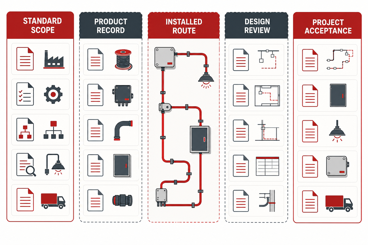
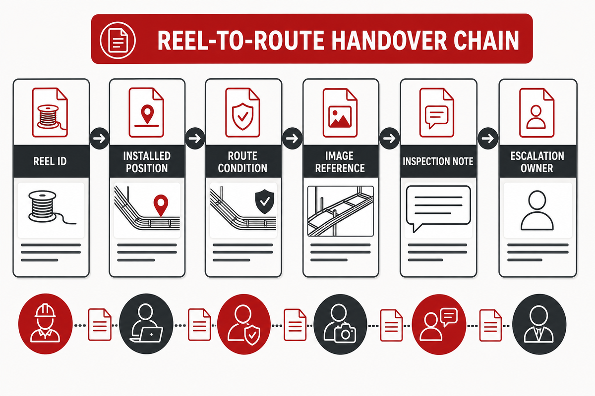
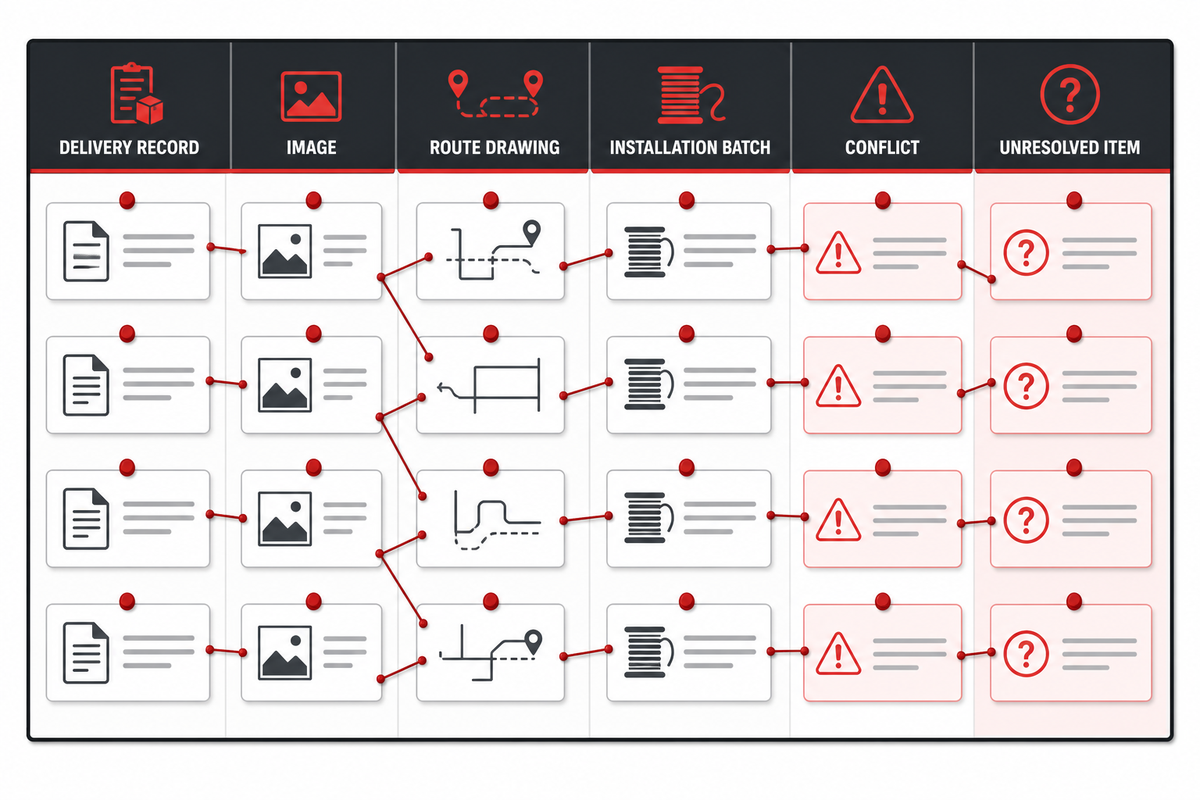
The central idea is the Desert Cable Evidence Trail: a short record that connects a reel or batch identity, an installed location, visible route conditions, inspection observations, and an unresolved-item owner. The record gives a project team something more durable than a generic claim that a cable is “desert ready.”
Scope and safety boundary: This is a de-energized, visual, and document-based walkdown guide. This guide isn’t intended to include electrical testing, energized work, opening equipment for inspection, connector disassembly, or acceptance decisions. These actions are within the approved project procedures and are the responsibility of qualified personnel.
Start With a Desert Exposure Record, Not a Cable Label
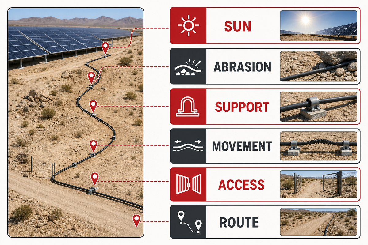
‘Desert’ combines a lot of exposure and installation terms, not a single product definition. A cable may be exposed to direct sun but not abrasive surfaces. One segment may be supported above grade but pass through a zone with repeated movement. It may be buried or run inside a conduit. It may be attached to tracker hardware and accessible to vehicles/maintenance personnel. Useful field records display the separate exposure conditions before someone draws a product or maintenance conclusion. For product-family context, the solar PV cable hub sits upstream of this inspection guide; it does not replace a route-specific record.
For each segment, record what’s observed and what can be confirmed:
Whether it’s exposed, protected, buried, in a raceway, or attached to equipment.
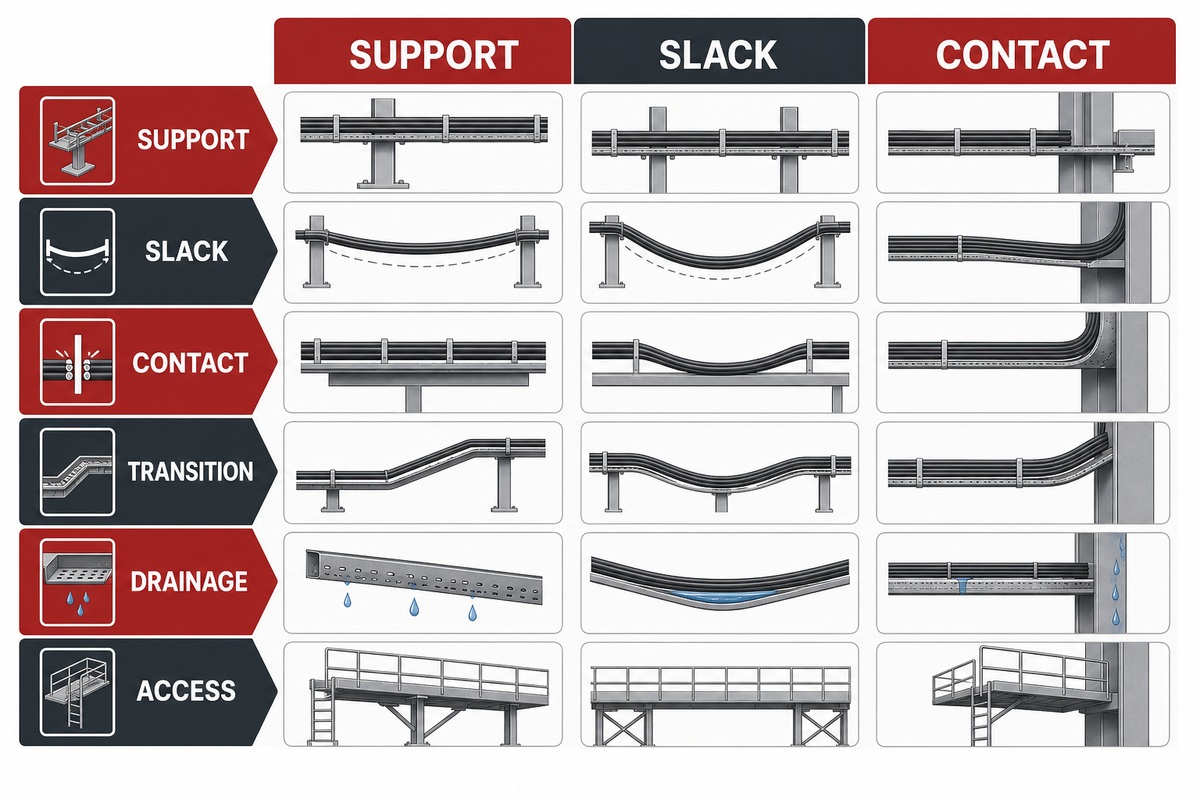
Its support system, spacing, and whether it contains ties/clips or contact points that are sharp and/or moving.
Where cable slack or bend transitions, joints, connector interfaces, or entry points are located.
Whether sand accumulation, cleaning, vehicle access, wildlife, water pathways, or maintenance access could affect that segment.
What is known from drawings and delivery records, and what remains unknown or unverified.
The information provided here isn’t a substitute for a design review. Rather, this information is a way to support a review of design, should the need arise, in the future. The U.S. Department of Energy describes cable management as an installation-and-operation issue, including cable length, bundling, bend-radius limits, insulation selection, and support practices. This is a good reminder that each of the route conditions should have their own record, as opposed to being included in a claim. U.S. Department of Energy – cable management guidance
For broader photovoltaic asset planning, DOE also frames durability and performance around site and life-cycle considerations rather than a single component label. Its performance-and-longevity overview provides that wider context; this guide remains limited to cable-route evidence.
Separate Standard Scope From a Site-Specific Approval
Field acceptance and standards language respond to different queries. The public IECEE listing for IEC 62930:2017 describes a scope for specified single-core, cross-linked insulated and sheathed cables used on the direct-current side of photovoltaic systems, with rated DC voltage up to 1.5 kV. It states a normal continuous maximum conductor temperature of 90°C and a limited permissible period at 120°C. Read the IECEE scope listing
The statements describe the scope of the standard. They do not establish that a particular delivered reel, installed route, bend, support point, connector interface, or project acceptance decision has been approved. The boundary should be preserved in plain language by a field guide.
Standard scope can inform what evidence to request. It cannot replace project-specific design review, product documentation, installation verification, or acceptance testing.
Keeping this in focus prevents two errors. The first is treating a standard reference as a warranty for an unknown installation. The second is asking the field team to make a product-selection decision from an inspection note. Neither team has the full evidence needed for that claim.
Turn Routing and Support Into an Installation Check
Routing isn’t an aesthetic decision. The route influences how easily an inspector can find the cable again, whether it can retain water or debris, what it can touch, and how it can move. A practical method is to examine the route in the order it was installed, rather than attempting to assess the entire array from a distance.
Field prompt
What to record
What it does not prove
What supports the cable here?
Clip, tie, hanger, tray, conduit, structure, or surface contact.
That the support system meets a project specification.
What can the cable contact?
Edges, hardware, moving equipment, ground, standing water, or access path.
The future wear rate or remaining cable life.
Where can it move?
Slack loops, transition points, tracker zones, vibration points, and service loops.
That movement is acceptable without engineering review.
Can this segment be found later?
Drawing reference, row or equipment identifier, photographs, and visible markers.
That every hidden segment has been inspected.
DOE shows that standard plastic ties used to secure a cable can fail prematurely due to heat, UV exposure, and chemical reactivity. It also mentions how motion along a slack route can damage a cable and create a pathway to faults and damage. That guidance is a reason to inspect support and contact points; it is not a project-specific prescription for a particular clip, interval, or cable construction. Where approved design inputs call for a thermal check, the ambient-temperature derating check can organize those inputs; it cannot approve the installed route.
Inspect Abrasion and Movement Points Before Energization
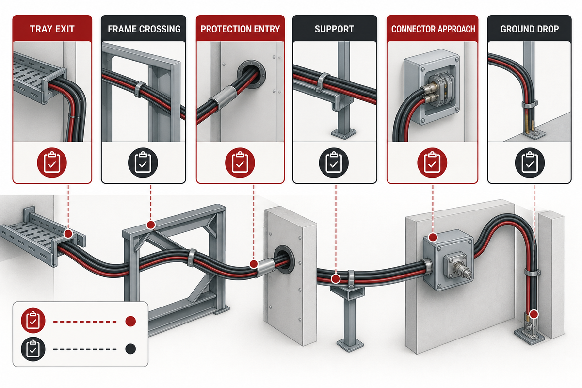
A good inspection is selective. Begin where one condition changes to another. It’s the place where a cable leaves a tray, crosses a frame, enters a conduit, passes a support, approaches a connector, reaches a moving assembly, or falls toward the ground. These changes are especially easy to overlook when a photograph shows only a broad array view.
Record your observations rather than making an assumption and stating a conclusion. For example, the observation is, “cable rests against an unprotected metal edge at row B-17.” The conclusion, “cable insulation is probably compromised,” may be correct, but more observations are needed to support that conclusion. The example protects the field technician and the person making the decision later by keeping observation separate from conclusion.
Use a simple three-state disposition:
Observed and acceptable to the approved project record: retain the evidence and location.
Observed but incomplete: identify the missing drawing, material record, test result, or owner.
Observed condition requires escalation: identify the location, condition, temporary protection if authorized, and decision owner. Do not make a product determination to close this note.
This record is particularly helpful for desert projects. Sand movement, cleaning, access work, and even equipment operation, may conceal the original installation condition. It helps distinguish a visible route problem from an electrical test problem; both may be important, but they’re different task activities.
Use the Desert Cable Evidence Trail at Handover
Handover should leave the next team with a navigable record, not a stack of unlabeled photographs. DOE commissioning guidance identifies system documentation, array testing, and whole-system performance testing as core commissioning elements for commercial, industrial, and utility-scale photovoltaic systems. Its commissioning overview is useful context: documentation and testing work together, and neither should be represented as the other.
For a desert cable route, a handover record can consist of five interrelated areas.
Supply identity: Delivery document, reel or batch reference where available, and the document owner.
Inspection status: What was visually checked, what test or commissioning record applies and what was outside the inspection scope.
Exception path: Open item, escalation owner, requested evidence, and closure reference.
The value is traceability, not a claim that the handover note certifies the installation. If a cable needs to be investigated at a later date, the team will know what was the case at handover and what was never verified.
Run the Field Walkdown in a Repeatable Order
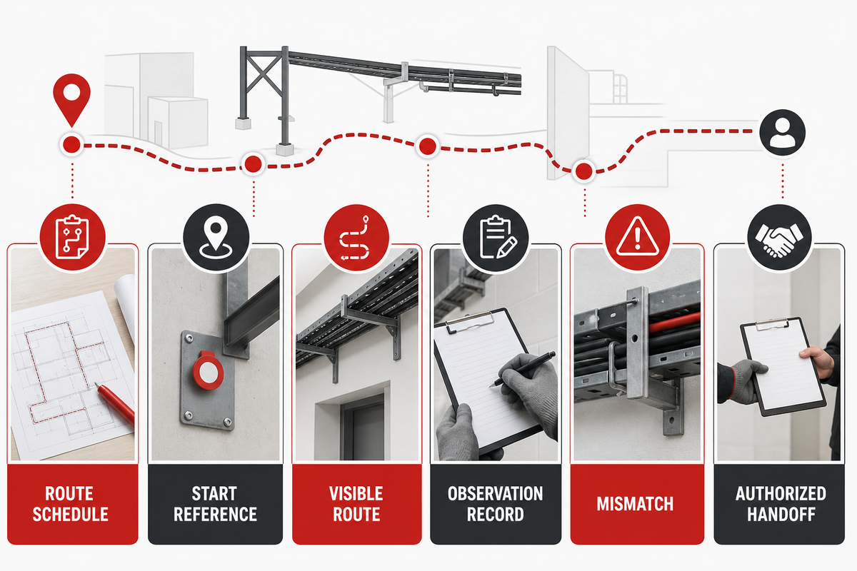
A walkdown has value if two people can follow the same sequence and reach the same locations. Start with the project drawing or route schedule, then walk from an identifiable electrical or structural reference rather than from an arbitrary point in the array. If the drawing cannot be reconciled with what is visible, record that mismatch before trying to solve it in the field.
Before the walkdown starts, confirm the work boundary in the project procedure. This sequence is limited to observations along the visible route. If the observation would require electrical testing, access to an energized area, opening an enclosure, disturbing a termination, or changing a support, stop the walkdown item and transfer it to the authorized project process.
Confirm the segment boundary. Note the row, circuit, equipment block, trench, or structure reference that defines the beginning and end of the observed segment.
Before looking for defects, follow supports. Note how the cable is carried, restrained, protected, or is allowed to move. This provides the reason and context for later observations.
Stop at transitions. Give special attention to entries, exits, bends, crossings, junctions, and moving interfaces. These are the places where a route description often becomes too general.
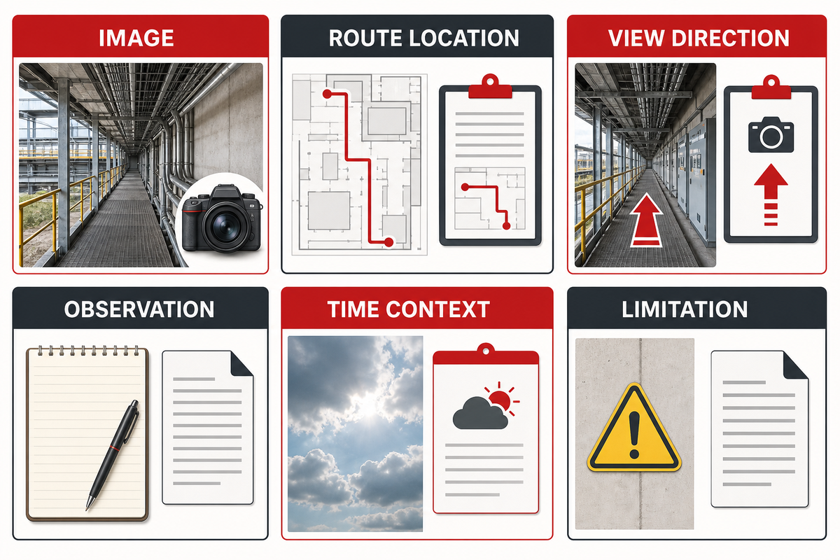
Take location-bearing evidence. An image should be paired with a route reference and a short observation. An image with no location or no identification may be difficult to use months later.
Separate visible condition from missing proof. A cable can look orderly while its delivery identity is missing. A complete document set can exist while an unprotected contact is present. Treat these as separate issues.
Assign the next decision. Close an item only when the responsible project record identifies the result. “Checked” isn’t an adequate closure statement if the question was actually whether a route or material record could be verified.
This order is meant to be practical. It doesn’t assign the duties of a project engineer to a field technician. It doesn’t place a commercial decision on a construction walkdown. It makes the information gap visible early enough for the right owner to act.
Make Photographs and Records Usable Together
Photographs are often abundant at project closeouts, yet still fail to answer basic questions, as the subject, direction, and location are unclear. A desert cable record does not need a complex software system to be useful. It needs a consistent naming approach that connects the image to the route and the observation.
Evidence type
Minimum useful description
Common failure to avoid
Route photograph
Location reference, viewing direction, and what segment is shown.
Using a wide array image with no identifiable cable segment.
Detail photograph
Support, edge, transition, or movement point and the visible condition.
Calling a condition “damage” when the image only shows contact or incomplete protection.
Delivery record
Document identifier, available reel or batch reference, and custody owner.
Assuming a nearby reel proves the identity of an installed segment.
Drawing reference
Revision, route identifier, and whether the route was physically checked against it.
Using a drawing revision without saying whether it reflects field installation.
Interface observation
Connector or termination location, visible condition, and any boundary that prevented further inspection.
Representing a visual observation as an electrical or torque verification.
Concealed-route limitation
Known conduit, raceway, burial, or inaccessible section and its last identifiable access point.
Claiming that a hidden segment was inspected because its endpoints were photographed.
Work-boundary reference
Applicable project procedure and the role that owns any electrical or access decision.
Using a field record as permission to open, test, alter, or energize equipment.
Test-record reference
Document identifier, responsible owner, and whether the visual record merely links to it.
Stating that a visual walkdown performed or passed an electrical test.
Escalation decision
Observed condition, decision owner, requested evidence, and controlled closure reference.
Treating an escalation note as technical acceptance or product approval.
Open-item record
Question, owner, target evidence, and closure reference.
Writing “to be checked” with no decision owner.
A good evidence trail also indicates its limits. It shows a cable’s visible path, but not cable’s concealed condition inside a raceway. It may link a delivery record to a shipment but not demonstrate a final connection torque. A precise limitation helps the next team select the right inspection or test instead of treating documentation as a universal proof.
Handle Missing or Conflicting Records Without Filling the Gap
In desert environments, some projects include long routes, repeated arrays, multiple installation teams, staged deliveries, and later access work. Discrepancies are not unusual under these conditions. The biggest concerns come from the quiet resolution of discrepancies with assumptions. The risk comes from quietly resolving it with an assumption: a photograph is assumed to belong to the nearest row, a delivery sheet is assumed to cover a later installation batch, or an old drawing is assumed to represent a changed route.
When evidence conflicts, document the inconsistency in a manner that’s capable of assessment.
What conflicts: for example, a drawing reference and visible route, or a delivery record and installed identity.
What’s directly observed: a position and a route condition; or a marking, a photograph, or a document identifier.
What isn’t established: don’t put forward a cause, a material designation, or a project approval that the evidence doesn’t support.
Who decides: name the role that resolves the issue in the project process.
What closes it: revised drawings, controlled material records, inspection records, test records, or other agreed project evidence.
This method isn’t the most satisfactory for getting a quick answer, but it does prevent a handover document from providing false certainty. It also means that an unresolved issue can be prioritized without converting the field team’s observation into a supplier claim or an engineering approval.
Use a Clear Escalation Threshold
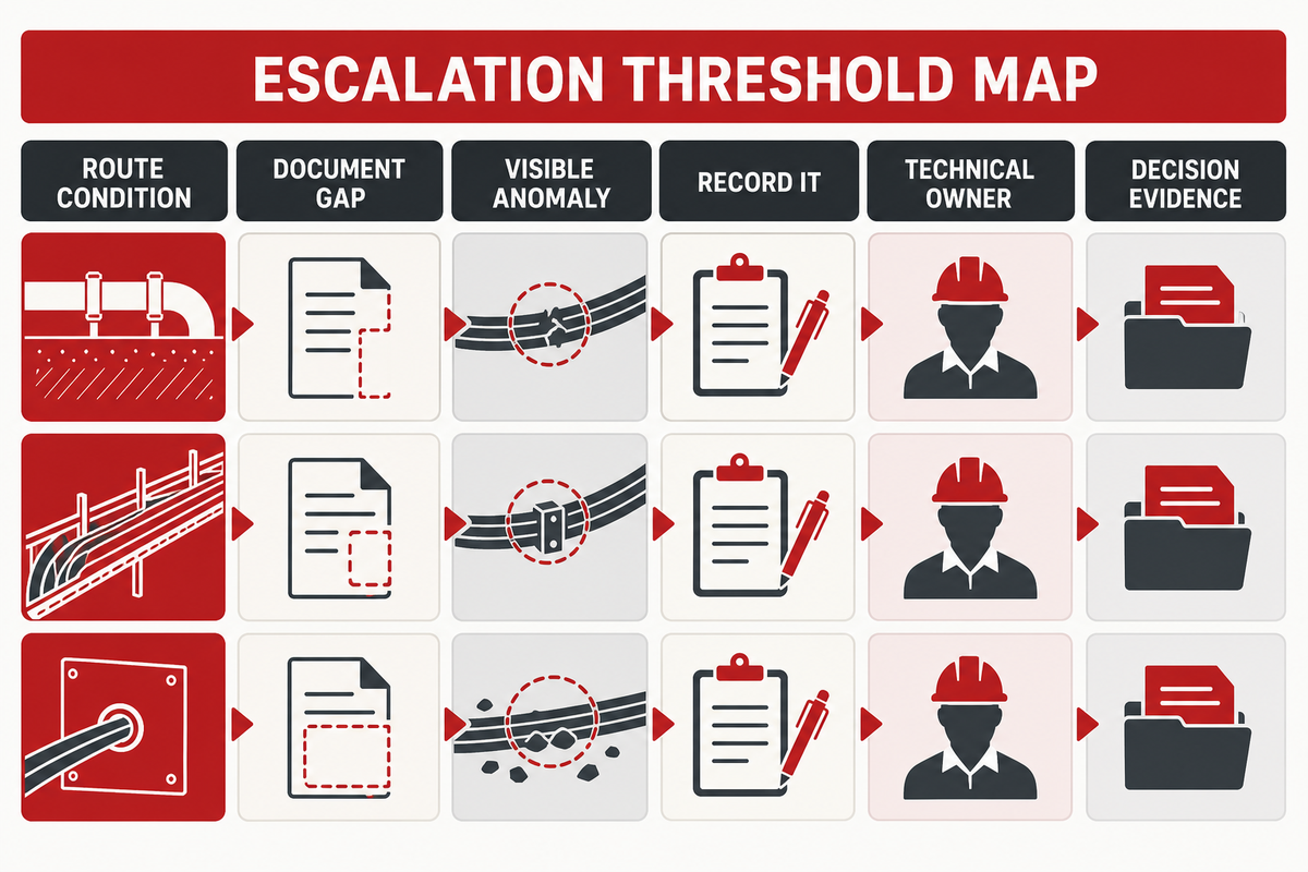
Not all observations should warrant the same response. The goal is not to create a long list of cable concerns. It is to identify when a route condition, a gap in the documentation, or a visible anomaly has crossed from a record to a decision by the responsible technical owner. A simple threshold can be set by answering the following three questions:
Are there visible contacts, losses of support, uncontrolled movement, insufficient protection, or other conditions that can’t be explained by the project record?
Is there a lack of a required identity, drawing reference, inspection, or test record for the segment being transferred?
Would continued work, energization, repair, or procurement require a technical evaluation that the field observer is not authorized to make?
If the response to any of the questions is affirmative, the next entry should name the condition and the owner. Speculation regarding a cable model or root cause isn’t needed. The distinction between inspection and approval as discussed in this article is very relevant now; the escalation is a request for evidence to make a case for a decision, and it isn’t a decision itself.
Answer Distance Questions With Design Inputs, Not a Universal Length
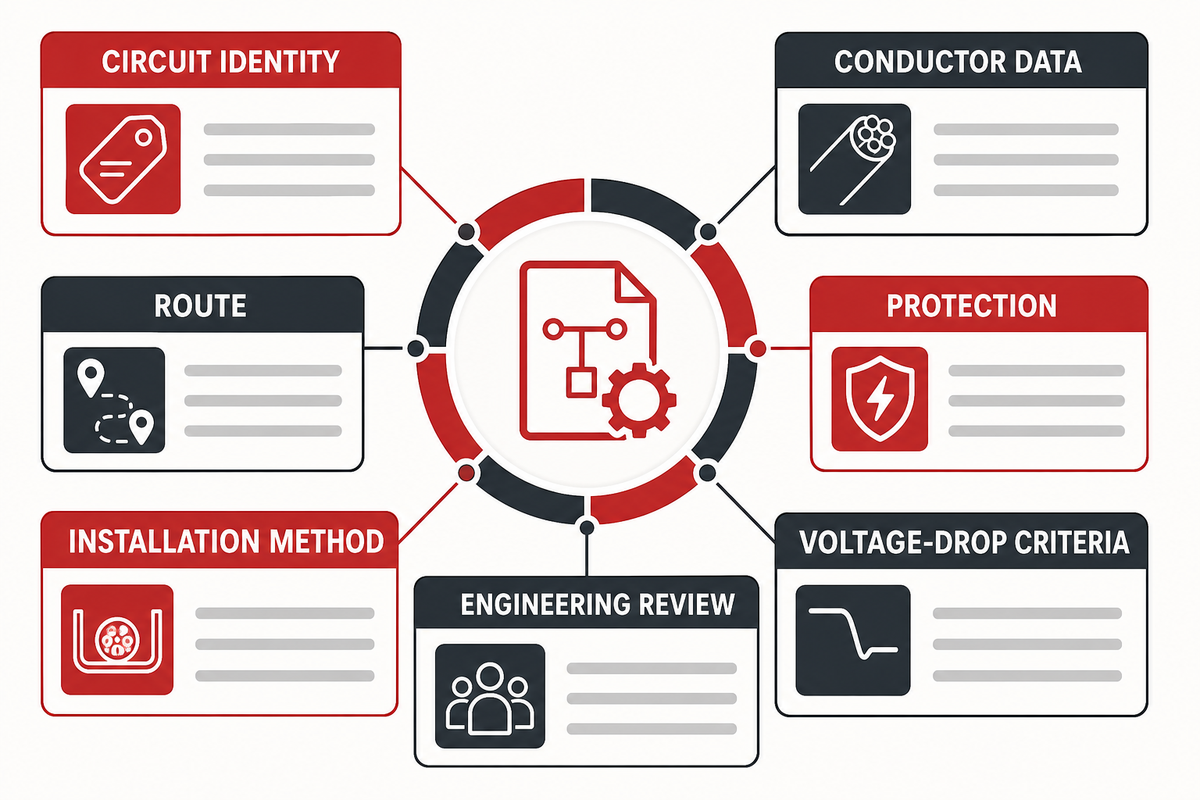
“How far are you able to run solar PV cable?” is a valid reader question, but this guide won’t specify a cable run length. This question needs to be addressed within the approved electrical design inputs: circuit definition, route, conductors, protective systems, installation method, and the project’s own criteria for voltage drop. A visual handover record can’t be a design decision.
Use this question as an opportunity for escalation. When approved inputs are available, the DC string voltage-drop and cross-section sizer can organize a calculation; it cannot turn a visual record into a design decision. Record circuit definition and route information, and then request the approved electrical design inputs and the engineering review. This elegantly separates an observation from a calculation. It also keeps an information guide from competing with a commercial solution page or a project design package.
Record and Escalate a Desert Solar Cable Problem
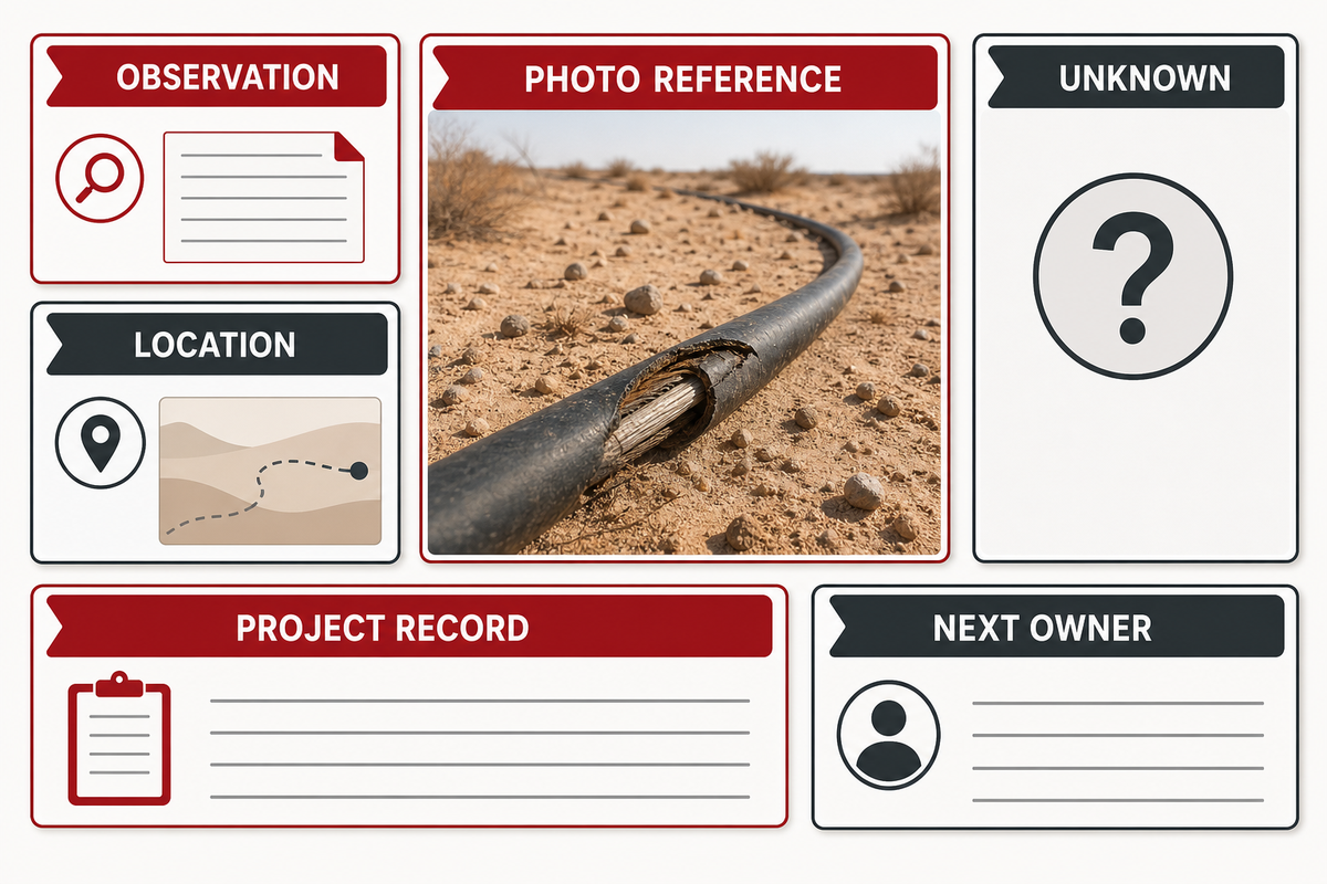
A thorough problem record includes observable language, location, and the next step to take. It doesn’t require the inspector to name a failure mechanism, or recommend a replacement. An example of this would be:
Location: tracker row identifier and photo reference. Observation: cable has contact with an edge in a movement zone; support detail cannot be confirmed from current record. Immediate status: no product diagnosis made; access and safe-work requirements remain project controlled. Escalation: send to the responsible installation or engineering owner with the route reference, supporting photographs, and requested confirmation.
Where an electrical test is relevant, direct the reader to the project record, rather than implying a visual check establishes the integrity of the electrical system. Where delivery identity is lacking, state that it’s lacking. An observed unknown is preferable over a fictitious completion.
Keep Patent and Product Claims in Their Proper Place
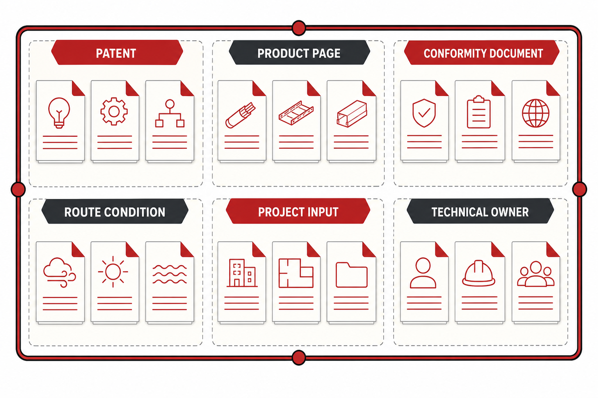
Some examples of discovery material include patents, product pages, and marketing descriptions. A design direction may be shown. A claimed construction may be shown. A question may be shown. Product-specific conformity documents can show that the stated requirements were assessed within their stated scope. None of these show that a cable is suited for a specific desert location, route, batch, or a service condition. The same holds true in the other direction: a field observation doesn’t demonstrate that a product design wasn’t adequate.
For these reasons, this article won’t compare models, claim a performance level, restate a service-life estimate, or derive a patent into a site recommendation. The appropriate next step is to combine the project input and product evidence that the pertaining technical owner requires.
When the Question Becomes Commercial
Proceed to a commercial discussion once the team needs a model, a quote, a certificate of scope, lot traceability, a documented construction of the product, or a project specific recommendation. Those requests require the project conditions and product records that a field inspection guide can’t provide. Teams that need application-level context can review solar cable solutions by application; this guide remains limited to evidence handover. For that step, refer to the desert solar cable solution details.
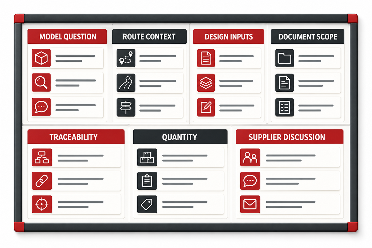
Shanghai Jinyou Jinhong Intelligent Electric Co., Ltd designs and manufactures renewable-energy cable solutions from Shanghai. A proper technical enquiry should include the installation case, the route type, the electrical design input, the required documentation, the quantity and the loading and delivery conditions. It allows the discussion to start on a factual basis rather than a presumptive basis.
Frequently Asked Questions
Does IEC 62930 approve a desert solar cable installation?
No. IEC 62930 defines the scope of a cable standard. IEC 62930 describes the scope of a cable standard; it is not a project acceptance record for an installed route. IECEE listing defines the standard’s applicability to cable construction and DC-side photovoltaic. However, the route conditions, installation, delivered product documentation, and project acceptance are different questions. To identify the evidence required, use the standard reference and maintain the project’s design, inspection, and commissioning records associated with the actual installation.
What should be checked visually before a desert PV system is energized?
Check the route where the cable changes support, crosses hardware, enters protection, approaches a connector, or passes through a movement zone. Record support method, visible slack, contact points, abrasion indicators, identification references, and missing documents. Note that this work neither substitutes for testing nor an engineering evaluation. It gives those later activities a reliable location and condition record, helping the team distinguish an observed route issue from an unproven diagnosis.
How far can a solar PV cable run?
No universal cable-run length belongs in this guide. Record the circuit and intended route. Obtain the approved design inputs and responsible engineering calculation. Current, resistance, cable length, and cable size affect wiring loss and voltage drop, so those inputs belong to the responsible engineering review rather than a visual handover record.
Are plastic cable ties enough for a desert installation?
This is a project-specific support decision, not a yes/no material decision. DOE points out that standard plastic ties may fail prematurely due to heat, UV exposure, and chemical exposure, and that failure may result in cable abrading against surrounding surfaces. The appropriate response is to inspect the actual support system, identify the applicable project requirement, and escalate any incomplete or damaged condition. Don’t make the assumption that the observation of failed ties means that ties aren’t acceptable for the project.
When should a field team contact a cable supplier?
Contact a supplier when a request requires evidence about a specific product (e.g., a model, a construction description, documentation of certification and traceability, and pricing, as well as the ability of the product to satisfy the requirements of the supplied project). Provide the route and the engineering inputs. A supplier can explain their product documentation, but a field guide can’t configure a product or validate the design of the project. Making that handoff clear helps avoid making the same decisions twice and helps prevent inspection notes from becoming unsupported procurement requests.
Shanghai Jinyou Jinhong Intelligent Electric Co., Ltd. has focused on new energy cable manufacturing since 2006, supporting solar/PV, energy storage, EV charging, and industrial or special-cable applications.
Use this guidance to prepare a clearer engineering or procurement discussion: operating environment, conductor and insulation expectations, route length, voltage, installation method, and project schedule.
Certificate evidence should be matched to the construction being specified. Public certificate evidence applies to H1Z2Z2-K solar cable constructions and should not be read as blanket certification for every JINYOU Cable product family.
PROJECT BRIEF
Move from article to specification
Share the application, required cable family, target standard, quantity range, and delivery window. The team can help structure the next engineering and procurement conversation.