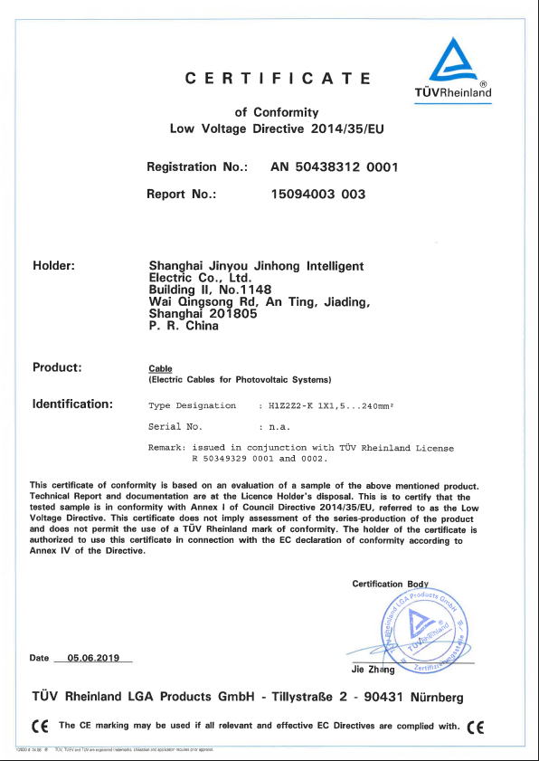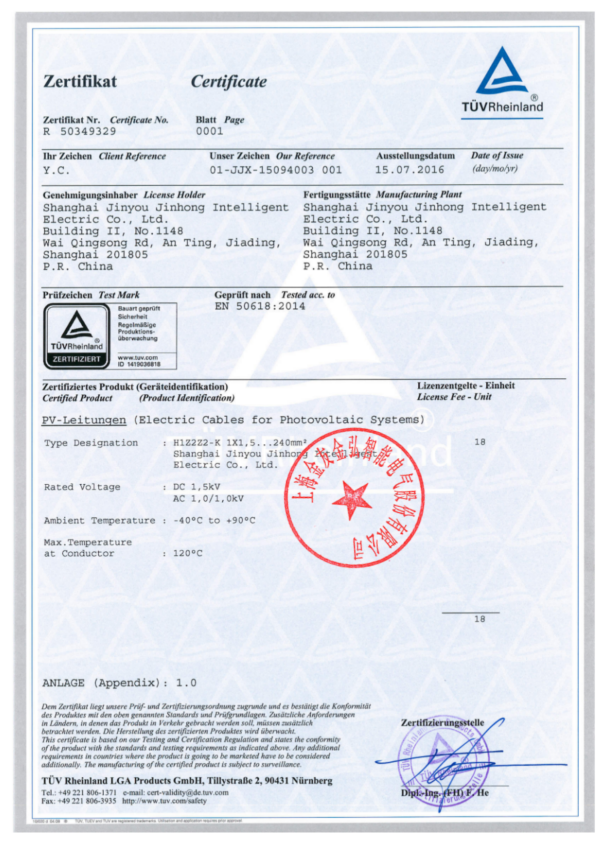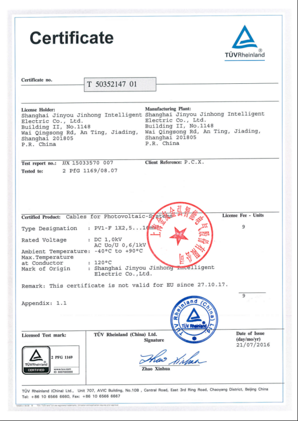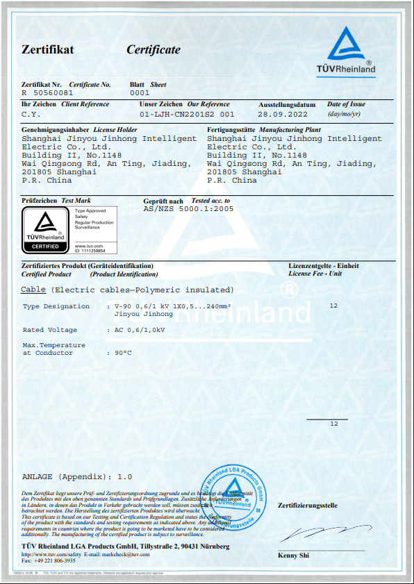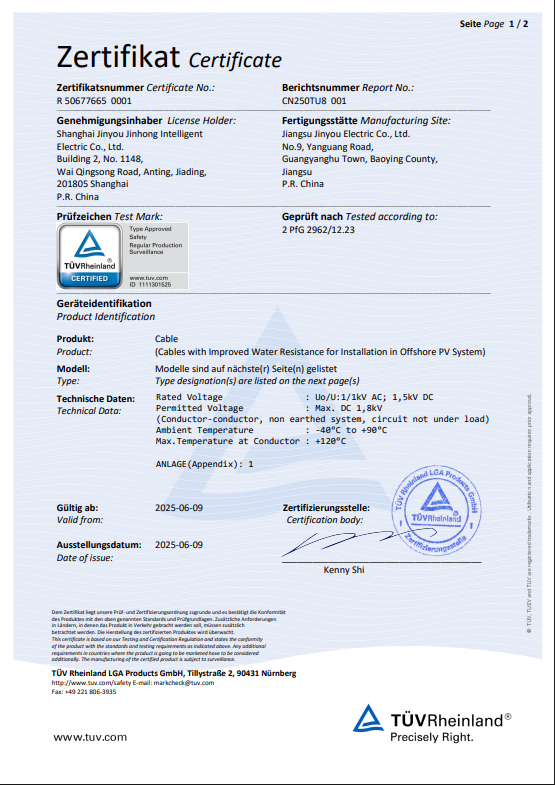
ISO Certified

EV High-Voltage Cable

EV High Voltage Cable for Automotive Power Systems

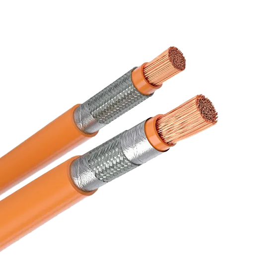
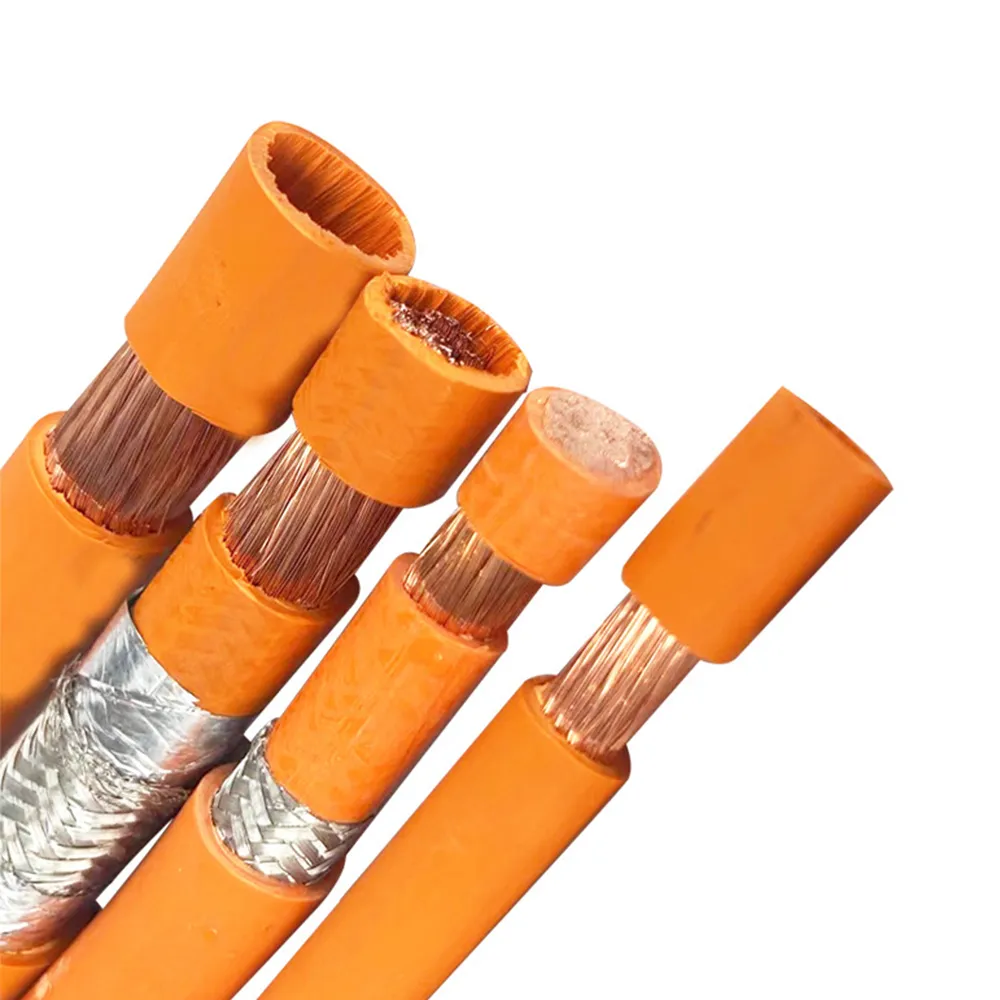
Jinyou Cable supplies a published shielded EV cable construction for vehicle main power circuits, with copper conductors, two insulation and sheath material paths, and braid-plus-foil shielding. Use the model data below to establish a starting point, then submit the current, route and acceptance requirements that decide project fit.

  • 1000 V AC / 1500 V DC published rating
  • XLPO or silicone material path
  • Tinned-copper braid plus foil
  • OEM specification review
Send Your EV HV Cable Requirements
Include the electrical load, route, ambient conditions, shield concept and target documents so the enquiry can be reviewed against one requirement set.
Engineered For High Performance
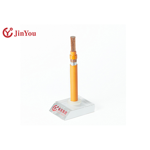
EV High Voltage Cable Construction
1000V AC / 1500V DC

Published Rating

XLPO / Silicone

Premium Material Path

Braid + Foil

Advanced Shielding

OEM Compliant

Specification Review

EV High Voltage Cable Applications and Selection Boundary

We publish EVYJ(P2)YJ-C for main power circuits of electric vehicles. The reference construction is relevant to high-voltage links where a buyer is defining a battery, power-distribution, inverter or motor route, but the route name alone does not select the conductor or prove installed performance.

Electrical definition

Start with maximum working voltage, continuous current, peak current and peak duration; a voltage label does not provide a usable current rating for every installation. Current selection needs the ambient temperature, bundle and duty conditions. Battery cables on stable DC routes and motor cables on PWM routes can present different thermal and shielding questions.

Mechanical route

A cable route has to account for bend radius, vibration and abrasion. State the route length, available envelope, fluid exposure and connector interfaces so the automotive high voltage cable decision stays tied to the vehicle rather than to a generic size chart.

EMC context

Identify PWM motor paths, nearby data or sensor circuits, frequency concerns and the planned shield termination. Shield construction is an input to validation, not a substitute for the installed-system test.

Acceptance evidence

Name the required standard edition, drawing, test schedule, sample plan, marking and delivery records. A buyer should distinguish the product description from the evidence needed to release a particular cable specification.

The selection boundary: a 400 V or 800 V vehicle architecture does not automatically approve a cable merely because its published DC rating is higher. Thermal loading, routing, interfaces and the project acceptance plan remain open decisions.

We design and manufacture custom OEM cables for project-specific requirements. We can review a customer-required wire structure against the project specification.

EVYJ(P2)YJ-C Construction Options

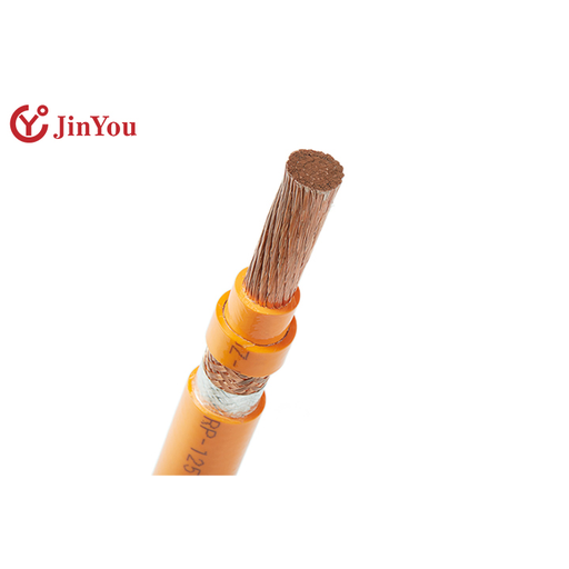
The published model is built as a layered automotive cable rather than a single insulation-only wire. Material selection should be written into the project specification so conductor, insulation, shield and sheath are reviewed as one construction.

1 · Conductor

Stranded soft bare copper

2 · Insulation

XLPO or silicone rubber

3 · Braid

Tinned copper

4 · Foil

Aluminium overlap layer

5 · Sheath

XLPO or silicone rubber

Copper Conductor

We use multi-stranded soft bare copper wires in the published conductor construction. Our published conductor constructions use nominal individual-wire diameters of 0.21 mm, 0.26 mm, 0.31 mm and 0.33 mm.

Insulation Path

We publish XLPO or silicone rubber as insulation options. The enquiry should name the temperature metric, fluid exposure, abrasion condition and validation standard rather than choose a polymer from one property alone.

Shield Path

The reference model combines a tinned-copper braid with an aluminium-foil layer. Termination, connector design and route-level EMC validation are outside what a construction percentage can prove.

Sheath Path

We publish XLPO or silicone rubber as sheath options. Final material selection belongs in the written specification with marking, colour, environmental exposure and test requirements.

EV HV Cable Requirement-to-Construction Matrix

This matrix is the handoff between a vehicle requirement and the published Jinyou construction. It does not calculate ampacity, predict shielding effectiveness or issue an approval; it shows which input must be settled before a construction can be reviewed.

EV-HV MATRIX / v1.0
EV HV Cable Requirement-to-Construction Matrix
Buyer requirement Published starting point Project evidence still needed
Working voltage We publish a 1000 V AC rating for EVYJ(P2)YJ-C. We publish a 1500 V DC rating for EVYJ(P2)YJ-C. Maximum operating and transient conditions, target standard and insulation coordination.
Current and heat Copper conductor constructions are listed by nominal cross-section and DC resistance. Continuous current, peak profile, ambient, bundle, cooling and allowable temperature rise.
Insulation and sheath XLPO or silicone rubber paths are published. Temperature metric, fluids, abrasion, outgassing constraints and requested test method.
Shield construction We publish tinned copper braid coverage above 85%. We publish aluminium foil overlap above 20%. Noise source, frequency range, termination, connector interface and vehicle-level EMC acceptance test.
Routing Fine-stranded conductor and layered construction. Length, envelope, bend requirement, vibration, clips, edge protection and service movement.
Release documents Published model and dimensional table. Drawing, agreed standard edition, sample plan, test report scope, marking and traceability fields.

“Start with the circuit and validation requirement, not the jacket colour. A braid and foil construction tells you how the cable is built; the project test plan tells you whether the installed system meets its EMC target.”

Jinyou Cable Engineering Team

Published EVYJ(P2)YJ-C Model Data

Our published EVYJ(P2)YJ-C table spans 1.5 mm² to 120 mm². We publish DC resistance at 20°C for each listed conductor construction. The rows below reproduce the exact model page’s conductor and finished-diameter data; the chosen row still needs project confirmation before it becomes an order specification.

Nominal area Conductor construction Max. conductor diameter Max. DC resistance at 20°C Published overall diameter
1.5 mm² 19 / 0.33 mm 1.80 mm 12.7 mΩ/m 4.9–5.3 mm
2.5 mm² 50 / 0.26 mm 2.20 mm 7.60 mΩ/m 5.5–6.1 mm
4 mm² 56 / 0.31 mm 2.80 mm 4.71 mΩ/m 6.6–7.2 mm
6 mm² 84 / 0.31 mm 3.40 mm 3.14 mΩ/m 7.2–7.8 mm
10 mm² 322 / 0.21 mm 4.50 mm 1.82 mΩ/m 9.1–9.7 mm
16 mm² 512 / 0.21 mm 6.30 mm 1.16 mΩ/m 11.1–11.7 mm
25 mm² 798 / 0.21 mm 7.80 mm 0.743 mΩ/m 13.4–14.0 mm
35 mm² 1128 / 0.21 mm 9.00 mm 0.527 mΩ/m 14.8–15.4 mm
50 mm² 1615 / 0.21 mm 10.50 mm 0.368 mΩ/m 16.7–17.5 mm
70 mm² 2294 / 0.21 mm 12.50 mm 0.259 mΩ/m 18.9–19.7 mm
95 mm² 3034 / 0.21 mm 14.80 mm 0.196 mΩ/m 21.6–22.4 mm
120 mm² 3774 / 0.21 mm 16.50 mm 0.153 mΩ/m 23.3–24.1 mm
Published EVYJ(P2)YJ-C Model Data

This table does not provide current capacity or minimum bend radius. Those values require a defined construction, thermal condition and acceptance method.

Prepare a Reviewable EV HV Cable Quote

Custom EV cable price follows the agreed conductor cross-section, copper construction, insulation and sheath system, shield, cut length, marking, quantity and documentation. Jinyou confirms availability, quotation validity and schedule in the written project response; this page does not publish a fixed price, MOQ or lead-time promise.

Voltage and current profile

Defines the electrical and thermal problem instead of relying on a platform label.
Working voltage, continuous current, peak current and duration.

Route and environment

Exposes length, packaging, bend, vibration, abrasion, fluid and ambient constraints.
Route drawing, 3D envelope or dimensioned sketch.

Construction preference

Separates material and shield choices from their required acceptance evidence.
XLPO or silicone preference, conductor area, shield and termination note.

Interface definition

Keeps finished diameter and conductor construction aligned with seals, terminals and connectors.
Connector drawing, terminal specification or vehicle cable interface control document.

Validation and records

Prevents a published product description from being mistaken for project release evidence.
Standard edition, sample quantity, test list, marking and traceability fields.

Commercial scope

Gives the quote a shared quantity, delivery destination and packaging basis.
Annual and release quantities, cut lengths, packaging and destination.

Requirement and Acceptance Boundaries

Procurement risk arises because model data, test methods and installed-system evidence answer different questions. Jinyou Cable publishes the product starting point; the buyer still sets acceptance criteria under the named ISO or vehicle specification. ISO 19642 separates cable vocabulary, test methods and product requirements across different parts of the series.

Keep the evidence layers separate. The honest distinction is that a published construction is not a test report. Unlike a generic “1500 V” filter, this page separates the model row from project evidence.

Published product evidence

Model, application, rated voltage, construction and dimensional rows from the exact Jinyou product page can support the first specification discussion.

Project acceptance evidence

The buyer should identify the required edition, sample, electrical, mechanical, environmental and EMC tests, plus the report fields needed for approval.

Installed-system evidence

Vehicle routing, connector termination, thermal load and EMC behaviour belong to the cable path as installed. They cannot be inferred from a braid or foil percentage.

Jinyou Cable describes its Shanghai factory as equipped for automated production and testing. That factory context supports custom OEM review; it does not prove a particular project test, certificate or product release.

Document the metric, not just the word. “Temperature rating,” “shielding” and “flexibility” are incomplete acceptance criteria until the test method, condition and pass/fail boundary are named.

How We Work: Specification Review Path

This is the buyer-facing path from an open requirement to a reviewable cable specification. It describes the information exchange, not an unverified promise about internal production timing.

Define the circuit

by recording the voltage, continuous and peak current, peak duration, route and interfaces.

Define the environment.

Add ambient temperature, bundle, cooling, vibration, abrasion, fluids and service movement.

Choose a starting construction.

Reference an EVYJ(P2)YJ-C row or submit the required conductor, insulation, shield and sheath.

Set the acceptance plan.

Name the standards, edition, tests, samples, reports, marking and traceability fields.

Align the commercial basis.

State quantity, cut length, packaging and delivery destination for one comparable quote.

Release only the agreed specification.

Treat the confirmed drawing and written acceptance criteria as the order boundary.

Where a Published Cable Rating Is Not Enough

A wrong assumption can expose an 800 V vehicle programme to a cable mismatch. A published EV HV cable row is a useful starting point, but it should not be stretched into an answer it does not contain. The alternatives below keep the decision moving without inventing a value.

A higher voltage label is not a substitute for thermal selection, and XLPO and silicone are not interchangeable by name alone. More braid coverage buys you a stated construction percentage, not vehicle-level EMC proof. Where to look instead: the route, connector, termination and test plan.

Where a Published Cable Rating Is Not Enough - EV High-Voltage Cable
Situation Why the published row is insufficient Next action
Current profile is missing Voltage and conductor area do not establish temperature rise for an unknown duty and route. Provide continuous current, peak current, duration, ambient, bundle and cooling data.
Only braid coverage is specified Coverage describes construction, while installed EMC also depends on frequency, termination, connectors and routing. Use the shielding brief and name the vehicle-level acceptance method.
The route is an external charging lead In-vehicle HV cable and EV charging cable face different handling, interface and standards questions. Move the enquiry to the charging-cable family and state AC/DC charging use.
A temperature class is copied from an old page A label without a current datasheet, standard edition and test metric can create a false equivalence. Submit the required temperature metric and request current project evidence.

EV High-Voltage Cable FAQs

Jinyou’s exact model page publishes 1000 V AC and 1500 V DC. Those values are product ratings, not a complete vehicle-system approval or a substitute for the project’s insulation-coordination review.
No. It establishes one voltage boundary, while current, duty, temperature, routing, bend, interfaces, shielding and the acceptance plan still have to be checked for the vehicle.
The published table spans 1.5 mm² through 120 mm². Each row has its own strand construction, maximum conductor diameter, DC resistance at 20°C and finished-diameter band.
No. A current answer requires the selected construction plus the continuous and peak profile, ambient temperature, bundle, cooling and allowable temperature-rise method.
No. The published values—braid above 85% and foil overlap above 20%—describe construction. EMC evidence must address the full cable path, terminations, connectors, frequency context and test method.
No. Both are published options, but the project must name the relevant thermal, chemical, abrasion, routing and validation conditions before material selection.
No. This page addresses an in-vehicle main-power cable model. Jinyou lists external EV charging cables as a separate product family with a different application and specification path.
ISO 19642-9:2019 covers screened or unscreened copper-conductor road-vehicle cables in voltage groups that include 1000 V AC and 1500 V DC. Citing its scope does not claim that this model has passed every ISO test.
Send the voltage, continuous and peak current, peak duration, route, ambient and bundle conditions, conductor preference, shield and termination concept, connector interfaces, quantity, cut length and acceptance documents.
Yes. The exact model page permits a customer-required wire structure, and the project still needs a written specification review to confirm the feasible construction and acceptance evidence.