Get in touch with JINYOU Cable Company

-
CALL US +86 181 1623 2461
-
EMAIL sales@jinyougroup.cn
Instrumentation Cable Specification for Industrial Signal and Control Systems
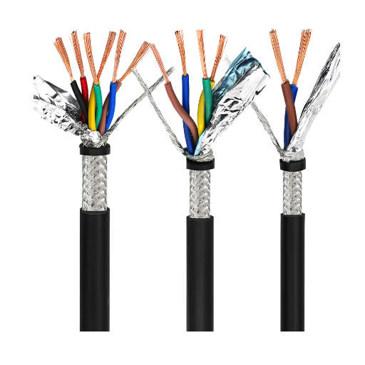
Instrumentation cable is cable built to serve low-level measurement, control and signal circuits between field instruments, junction points and control equipment, with its pair or triad layout, shielding and jacket chosen for the signal rather than for power delivery. Selection starts with the signal, route, motion and evidence the installation must carry.
- Separate signal integrity, mechanical duty and installation classification before choosing a cable family.
- Treat pair or triad layout, shielding, jacket and route as one specification rather than isolated catalogue words.
- Keep company-level manufacturing scope separate from model ratings, listings and test reports.
The engineering principle:
select the signal, route and duty cycle before you select the cable family. This self-service brief gives your team a clean set of decisions for its internal specification review.
Instrumentation Cable Scope at a Glance
Application Boundary for Instrumentation Cable
A broad cable label creates a wrong-selection risk when a low-level analog loop, a process control cable and a moving robot circuit are treated as one duty. The gap usually appears between the signal schedule, the physical route and the standard named in the project documents.
SELECTION BOUNDARY
Signal and circuit role
Analog, digital, thermocouple and fieldbus circuits react differently to noise, reference-junction and impedance conditions.
Useful screening question
What must remain measurable at the instrument after the route is installed?
Core, pair or triad count
A multi pair instrumentation cable can simplify segregation, while a single pair may reduce unused material and termination work.
Useful screening question
Does the cable schedule show spare cores, dedicated returns and drain-wire treatment?
Route and environment
Indoor, outdoor, marine/offshore, tray, raceway and hazardous-area routes impose different construction and approval inputs.
Useful screening question
Which room, tray, gland and authority having jurisdiction govern the run?
Motion duty
Fixed installation, continuous flex and torsional robot motion load the conductor, lay and jacket in different ways.
Useful screening question
Does the route move linearly, bend in a track or twist around an axis?
Approval & Documentation
A catalogue description is not the same as a model-specific construction drawing, test report or listing.
Useful screening question
Which revision, test method and lot record must be filed for approval?
IEC 60092-376:2025 is a useful reminder that control and instrumentation can share one defined sector scope: it covers screened and unscreened cables for ship and offshore fixed installations at 150/250 V (300 V).[1] That marine boundary does not become a universal rule for every industrial plant.
Industrial control cable
Use the circuit function and route class to decide whether the construction belongs in a process control, signaling or instrumentation schedule.
Special cable programs
Use the environmental and mechanical inputs to define an industrial special cable brief instead of treating “special” as a performance rating.
Approval handoff
Carry the chosen standard, revision, test method and installation boundary into the same controlled document.
Shielding, Pairs and Construction Inputs
Shielding is a construction choice, not an installed-system EMC certificate. NIST describes shielding performance as a function of material properties and details such as joints, seams, apertures and geometry, while NASA guidance highlights the impedance of the termination path.[4][5]
The Signal-Path Specification Matrix treats the signal path as one object: the run from the instrument terminal through the pair, shield, drain wire and termination to the receiving input. Each row names a construction input, the failure mode when it is left vague, the evidence a buyer should request, and the conclusion that field cannot support on its own.
The Signal-Path Specification Matrix — eight construction inputs, one signal path
| Construction input | Failure mode when it is vague | Evidence to request | What this field cannot tell you |
|---|---|---|---|
| Conductor material and class | Resistance, flexibility and termination assumptions drift between suppliers. | Construction sheet, conductor material such as copper, IEC 60228 conductor class and nominal size in mm² or AWG. | Current-carrying capacity — the nominal cross-section alone does not set ampacity for the installed conditions. |
| Insulation system | Voltage, temperature and chemical assumptions are copied from the wrong family. | Exact insulation material such as PVC or XLPE, rated voltage as the governing standard defines it (for example 300 V or 600 V; product listings often print this as 300V or 600V), wall/construction drawing and test scope. | The circuit’s own voltage class or the installation rules of the site. |
| Pair, triad and lay | Signal return and crosstalk targets are left to the installer. | Core map, pair or triad count, lay direction, pair identification, and whether a multi pair instrumentation cable or single pairs serve the schedule. | Immunity in the installed route, which also depends on separation and bonding. |
| Shield type and coverage | A “shielded instrumentation cable” label is mistaken for proof of EMC in the installed route. | Foil, braid, combination or no shield, the coverage basis, and any IEC 61726:2022 screening-attenuation method named in the specification.[8] | The installed EMC result; termination, bonding and geometry set that outcome.[4][5] |
| Drain wire and screen termination | The drain is used as a signal return by default, or terminated at both ends without a bonding plan. | Where the drain terminates, whether it carries the signal return, and the termination hardware. | A universal one-end or two-end grounding rule; the answer follows the signal reference and cabinet bond. |
| Filler and separator | Unused cores, loop area and segregation are discovered after the cable is ordered. | Filler material, separator between pairs or groups, and the space kept for spare cores. | Crosstalk performance without the pair layout and the route. |
| Outer jacket and marking | Installation crew cannot match the reel to the approved schedule or environmental route. | Jacket material and exposure basis, print legend, colour code, revision and lot correlation. | Suitability for a route the specification never named. |
| Overall diameter and bend limits | Tray fill, gland size and bend path are checked after purchase. | Nominal overall diameter, minimum bend radius basis, and the motion duty the construction is meant for. | Continuous-flex or torsional endurance; that belongs to the Duty-Cycle Split below. |
01
Installation Notice
Running instrumentation and power circuits in the same tray is acceptable only when the route, divider and manufacturer instructions line up. Shielding advice changes when the signal reference and cabinet bond change; a shield can reduce coupling while a poor termination still leaves a noise problem.
02
A shield label is not an installed EMC result
Jinyou Cable manufactures cables and uses sophisticated testing systems, but a construction label is not interchangeable with an installed EMC result. Use the shielding and route decision to expose the failure mode before approval.
Tray, Indoor, Outdoor and Hazardous-Area Routing
Routing determines what the cable must survive after it leaves the reel. The NEC’s Type ITC article (Article 727 in editions through 2020) covers instrumentation tray cable used on instrumentation and control circuits operating at 150 V or less and 5 A or less; NFPA’s public code-development record for that article is linked below, and the adopted edition and article number must be confirmed with the authority having jurisdiction.[6] OSHA requires hazardous-location equipment and wiring to be approved for the classified location and specific ignitable properties.[3]
Route condition
Decision gate
What the brief must name
Tray or raceway
Confirm the cable construction and listing match the adopted installation rules.
Tray type, support, separation, bend path and termination hardware.
Indoor process area
Control crosstalk and mechanical damage around power, drive and instrumentation runs.
Adjacent circuits, segregation method, panel entry and service loop.
Outdoor or wet route
Weather, moisture ingress, UV and jacket exposure become part of the selection.
Exposure, drainage, gland system, jacket material and maintenance access.
Marine or offshore route
Use the marine/offshore standard scope instead of transferring a land-plant assumption.
IEC 60092-376 edition, fixed-installation boundary and explosive-atmosphere interface.
Hazardous classified location
A cable family name does nothing for a missing area classification or an incompatible gland.
Class/Division or Zone, gas/dust group, temperature class, sealing and approval path.
Installation boundary
OSHA 1926.407 lists Class I, Division 1 and 2, Class II, Class III and Zone designations, and requires approval for the location and ignitable properties. A process control cable or industrial control cable is not approved for a hazardous area by name alone.
Route handoff
Keep route decisions visible in the cable schedule. A late change from indoor raceway to outdoor tray can require a different jacket, marking, gland and test package even when the signal is unchanged.
Specification Handoff and Commercial Scope
Pricing follows conductor composition, pair count, shielding, jacket, route, quantity and document scope rather than a generic catalogue label. The same factors influence installation cost, approval effort and the cost of an incremental change.
Inputs that keep a comparison fair
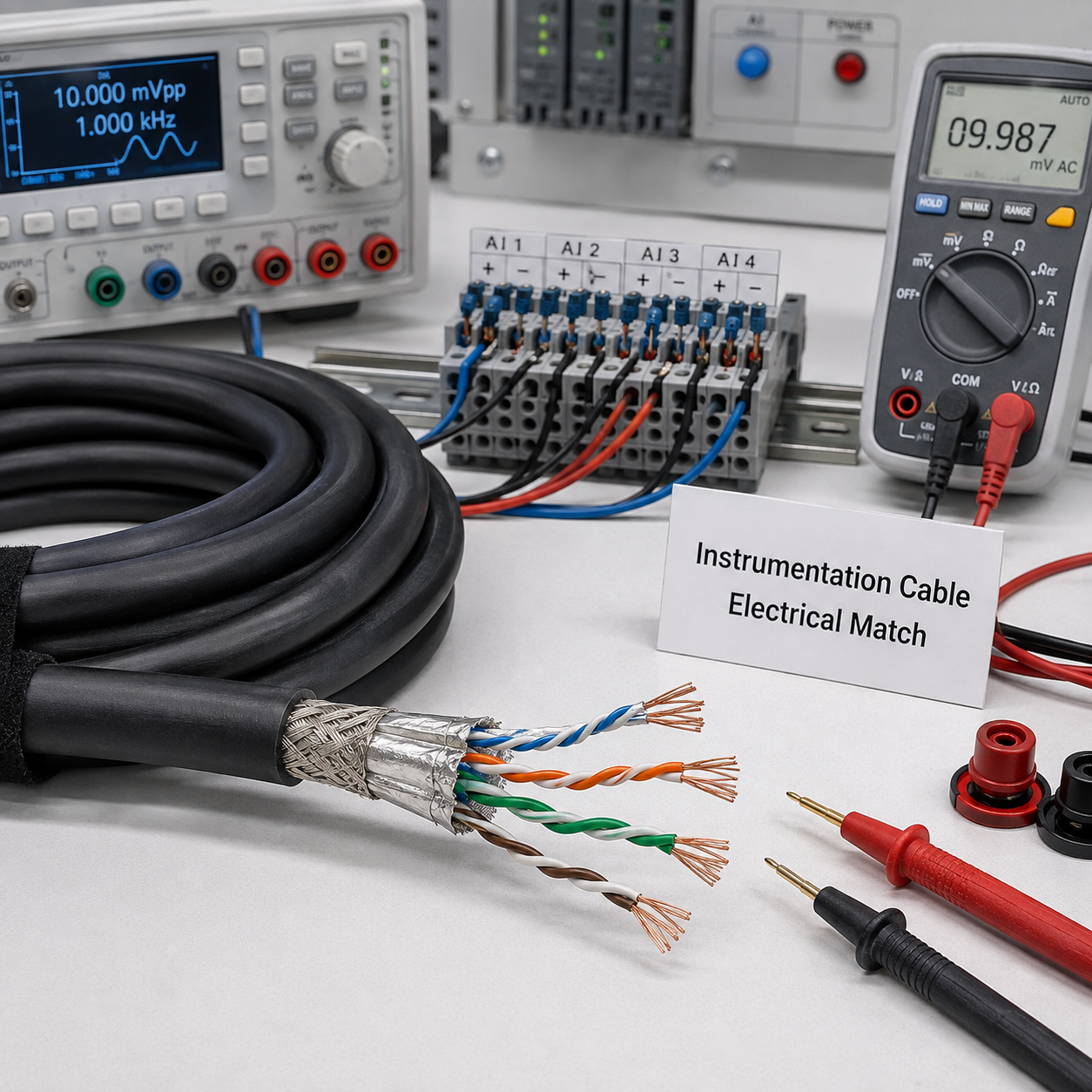
Input Group
Electrical
Write it as: Signal type, voltage/current context, pair/triad count, impedance or continuity requirement.
Reason: Prevents a lower-priced but electrically different offer.
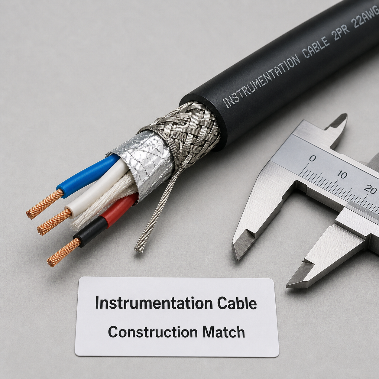
Input Group
Construction
Write it as: Conductor, insulation, shield, drain, filler, jacket, diameter and marking.
Reason: Creates an apples-to-apples line item.
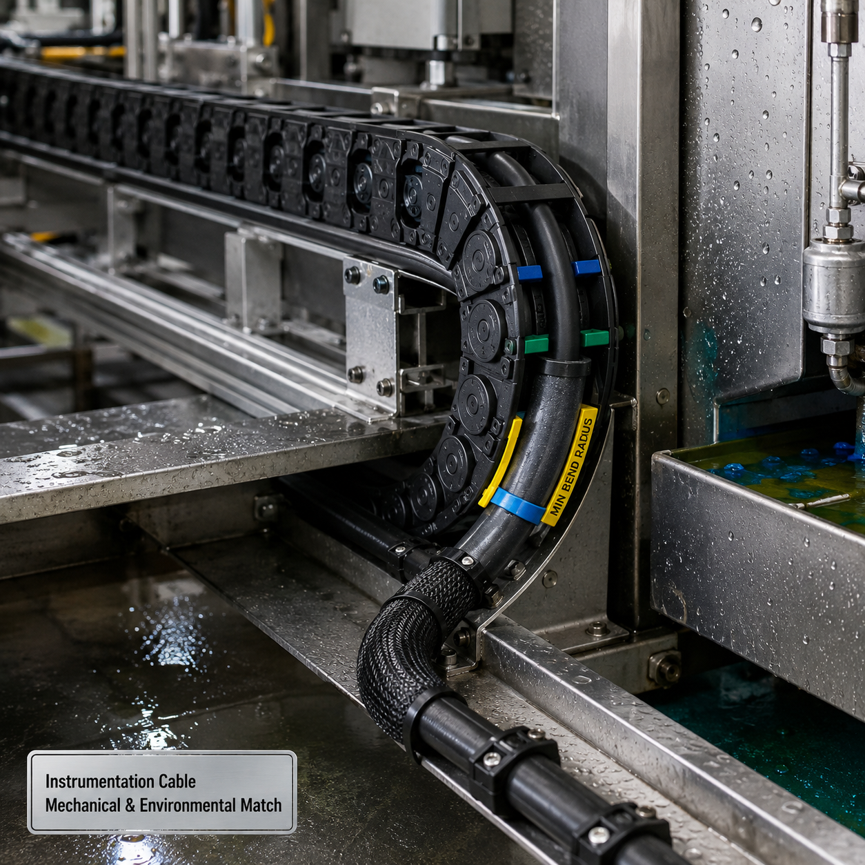
Input Group
Mechanical / Environmental
Write it as: Route, bend, flex/torsion axis, moisture, abrasion, chemicals and temperature exposure.
Reason: Stops a fixed cable from being substituted into a moving or harsh route.
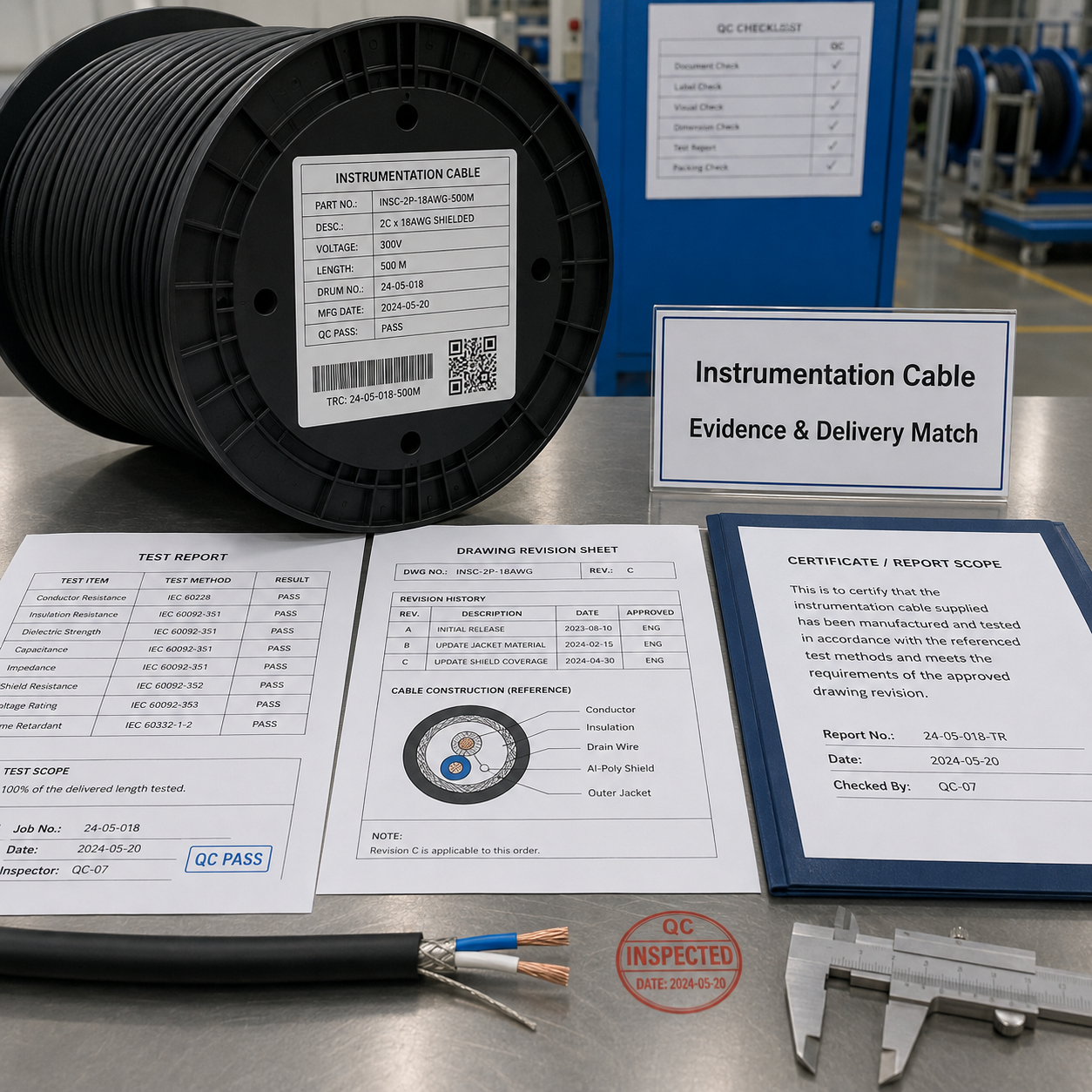
Input Group
Evidence and Delivery
Write it as: Drawing revision, test method, certificate/report scope, reel label and traceability fields.
Reason: Reduces approval delay and shipment mismatch.
The Duty-Cycle Split: Fixed, Flexing and Robot Cable
The Duty-Cycle Split is the rule that fixed installation, continuous flexing and torsional robot motion are specified, quoted and evidenced as three separate duties. The names robot cable, flexible robot cable and flexible control cable do not state a stress axis by themselves; they are not grades of one product.
The Duty-Cycle Split — three motion duties, three evidence boundaries
Fixed installation
Stress on the construction
Static bend at pull-in, then thermal and environmental exposure on a tray, in a raceway or in a classified area.
Evidence to request
Minimum bend radius basis, route class and the installation standard named in the schedule.
What cannot be inferred
Any flexing or torsion endurance; a fixed-installation cable has no motion rating to transfer.
Continuous flex in a cable track
Stress on the construction
Repeated bending around one axis, with routing, length, tension and track overfill recorded as failure factors.[10]
Evidence to request
Flex cycle basis, bend radius in motion, travel length, acceleration and the test method behind any cycle figure.
What cannot be inferred
Torsional endurance; a track-rated cable can still fail on a rotating axis.
Torsional robot motion
Stress on the construction
Twisting about the cable axis on a robot arm or wrist, which loads the lay, fillers and shield differently from linear flexing; published patent constructions use separate data and power units, filling and layered torsion-resistant structures for this duty.[11][12]
Evidence to request
Torsion angle per metre and direction, supported length, cycle basis and the mechanical test that produced any figure.
What cannot be inferred
A life rating for your work cell; cycle and angle inputs stay project data until a model-specific test report exists.
Quality Assurance and Traceability
Jinyou Cable uses sophisticated testing systems within a production environment equipped for controlled cable work. A quality decision is strongest when the requested test, acceptance criterion and lot identity are written before release.
Define the test plan
Identify the continuity, insulation, screening, mechanical or environmental tests the project requires.
Correlate the lot
Keep revision, reel or lot identity and the applicable test report together.
Release the handoff
Archive the approved specification and exceptions before installation.
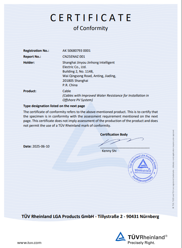
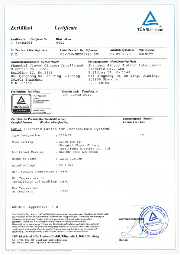
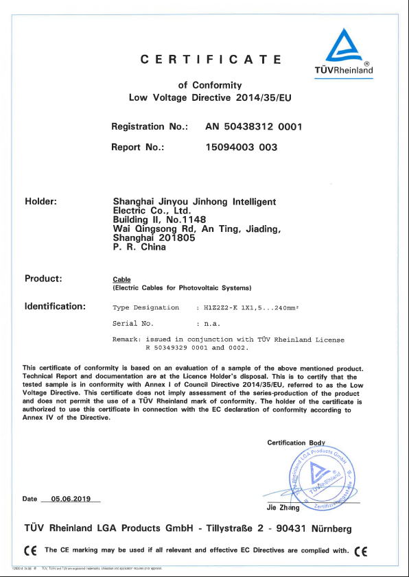
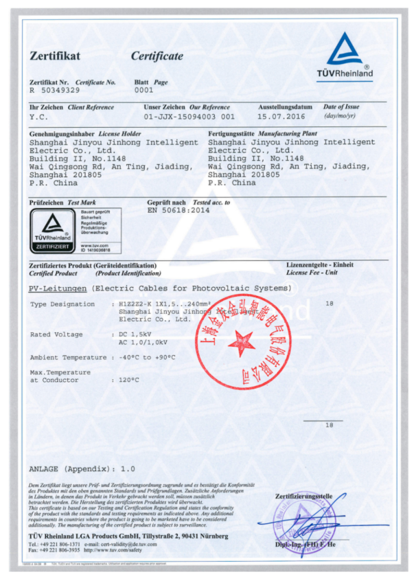
Instrumentation Cable Engineering & Specification Tools
01
Signal-Path Specification Checklist
Set the four decisions that determine whether a cable brief is ready for engineering review. The result is a scope check, not a product rating.
Access Tool02
Shielding and Route Decision
Route Analysis
Use the signal, nearby noise, bonding plan and route to expose the next engineering question. This tool never assigns a universal one-end or two-end shield rule.
Access Tool03
The Duty-Cycle Split: Cable Family Check
Separate fixed, linear-flex and torsional motion before a cable family is compared. Cycle and angle fields remain specification inputs; the tool does not create a life rating.
Access ToolKNOWLEDGE BASE
Instrumentation Cable Selection Boundaries
Engineering Guidelines & Technical Specifications
What is instrumentation cable used for?
Instrumentation cable carries measurement, control and low-level signal circuits between field instruments, junction points and control equipment. The signal schedule and route decide the construction.
What are instrumentation cable types?
Instrumentation cable types may be separated by signal role, pair or triad layout, shield arrangement, jacket and route. Start with the application rather than a generic family label.
How do instrumentation cable sizes affect selection?
Instrumentation cable sizes affect conductor resistance, pair count, bend path, tray fill and termination space. Record the electrical and mechanical limits together in the approved specification.
Is instrumentation cable the same as control cable?
Instrumentation cable vs control cable is a sector and application question, not a universal naming rule. IEC 60092-376:2025 places control and instrumentation circuits in one defined marine/offshore fixed-installation scope.
When do I need shielded instrumentation cable?
Choose a shield after reviewing signal sensitivity, adjacent noise sources, bonding and termination. A shielded instrumentation cable still needs a route and termination plan; NIST describes construction details as part of shielding performance. Work through the Signal-Path Specification Matrix above before the shield line is written.
What belongs in an instrumentation cable specification PDF?
An instrumentation cable specification PDF should identify construction, standard edition, route, marking, tests, report fields and revision. A document title without those fields is not a complete approval package.
What separates flexible robot cable manufacturers?
Flexible robot cable manufacturers should distinguish continuous flex from torsion and state the motion axis, routing and test basis. A flexible control cable is not automatically a robot cable.
What is the difference between robot cable types?
Robot cable types are separated by fixed, linear flex, torsional or combined motion; the Duty-Cycle Split treats each as its own specification and evidence boundary. The A3 robot-cable guidance recommends comparing the cable’s motion parameters with the actual work cell rather than choosing by appearance.[10]
How do process control cable types differ?
Process control cable types differ by signal role, pair/triad arrangement, shielding, route and approval scope. Keep process control cable and industrial control cable terms tied to the project schedule and named standard.
Can a hazardous-area cable be approved by name alone?
No. OSHA 1926.407 requires the classified location and the specific ignitable properties to be considered, with compatible approval and marking.
How should thermocouple cable be specified?
State the thermocouple type, extension or compensating role, identification and tolerance basis. IEC 60584-3:2021 defines the extension/compensating cable boundary and its relationship to the thermocouple e.m.f. reference.
How is instrumentation cable different from power cable?
Power cable is sized to deliver current at the system voltage; instrumentation cable is built around signal integrity, so pair or triad layout, shielding and drain treatment decide its construction, and segregation from power runs decides its route. The two share a tray only when the route, divider and manufacturer instructions allow it.
How should instrumentation cable be installed and terminated?
Follow the route class in the schedule: respect the bend radius basis, keep the separation and divider rules, and terminate the shield and drain exactly as the bonding plan states. NASA and NIST guidance place much of the achieved shielding result in termination and geometry rather than in the cable label.[4][5]
What are common instrumentation cable problems?
The recurring ones are noise coupling from a poorly terminated shield, a fixed or track-rated cable placed on a torsional robot axis, a cable specified by a hazardous-area name without a site classification, and quotes that cannot be compared because the specification left construction fields open. Each one maps to a check on this page.